Content .. 1886 1887 1888 1889 ..
Isuzu D-Max / Isuzu Rodeo (TFR/TFS). Manual - part 1888
7A3-6 ON-VEHICLE SERVICE (JR405E)
INHIBITOR SWITCH
The inhibitor switch is attached to the right side of the
transmission.
Inspect
1. Block the wheels.
2. Disconnect the negative battery cable.
3. Disconnect the harness connectors.
4. Use a ohmmeter to check the inhibitor switch
continuity between the following terminals as shown
in figure.
5. Place the select lever in the “N” range.
249R300001
6. Move the select lever to either side.
Check the inhibitor switch continuity between the
terminals shown in Step (4).
The continuity readings should remain fairly steady
as the select lever is moved.
If there is no continuity or the continuity is
intermittent, the inhibitor switch must be adjusted.
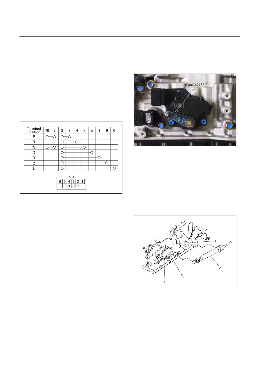
Adjust
1. Disconnect the shift calbe from the lever.
2. Loosen the inhibitor switch bolts.
3. Use the inhibitor switch set plate to align the neutral
holes (manual shaft and inhibitor switch).
Turn the inhibitor switch to adjust it.
Inibitor switch set plate: 5-8840-2763-0
Note:
Inhibitor switch adjustment is very important.
If the inibitor switch is not correctly adjusted, the
automatic transmission will not function normally.
4. Tighten the 2 inhibitor switch bolts to the specified
touque.
Torque:
5.5
N·m (48 lb·in)
47INH-SW01
5. Connect the shift cable to the lever.
6. Connect the harness connector.
Remove or Disconnect
1. Remove the cable bracket (1) from the transmission.
2. Disconnect the shift cable (2) from the lever (3).
3. Disconnect the harness connectors.
4. Remove the inhibitor switch bolts.
5.
Remove the inhibitor switch (4) from the
transmission.
238R300001