Isuzu D-Max / Isuzu Rodeo (TFR/TFS). Manual - part 1734


  Index      Ford     Isuzu D-Max / Isuzu Rodeo TFR/TFS series - service repair manual 1997-2003 year


Search            


Content   ..  1732  1733  1734  1735   ..


Isuzu D-Max / Isuzu Rodeo (TFR/TFS). Manual - part 1734


CONSTRUCTION AND FUNCTION  7A1-33


LEARNING CONTROL 

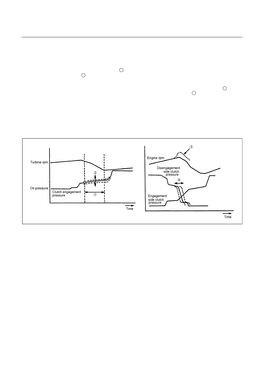
 Oil pressure control timing is optimally corrected at the time of clutch engagement and disengagement 

and controlled to bring the speed-change time to the value preset to the TCM and compensate the 
changes of the engine performance and changes of the transmission with time. 

 When the gear is shifted, the clutch pressure 

2

 is optimally corrected so that the speed-change time is as 

near as the target value 

1

 preset to the TCM and the changes in the engine performance and the 

changes of the transmission with time can be compensated based on the past speed-change results. 

 When the clutch is operated to shift the gear, the time of the clutch oil pressure release timing 

4

 on the 

disengagement side is optimally corrected so that the changes of the engine rpm 

3

 is optimum.


Note: 

 When the battery terminal is disconnected, contents of learning are cleared and resultantly the speed 

change shock may increase.  After the vehicle has traveled, learning is repeated and the shock 
decreases gradually.


 Figure 53. Learning Control 

7A1-34  CONSTRUCTION AND FUNCTION


MAJOR INPUT/OUTPUT COMPONENT AND THEIR FUNCTIONS 

Speed sensor 

Detects output shaft revolution and sends rpm signal to TCM. 

Turbine sensor 

Detects input shaft revolution and sends rpm signal to TCM. 

Engine speed sensor 

Inputs engine revolution from engine control computer. 

Brake switch 

Detects brake pedal operated by the driver and sends signal to 
TCM. 

Inhibitor switch 

Detects select lever position and sends signal to TCM. 

Mode select switch 

Detects "Power Drive" or "3rd Start" selected by the driver and 
sends signal to TCM. 

4L switch (4WD Only) 

Inputs 4L mode from transfer control computer. 

ATF thermo sensor 

Detects ATF temperature and sends signal to TCM. 

High clutch oil pressure switch 

Detects high clutch supply oil pressure and sends signal to 
TCM. 

2-4 brake oil pressure switch 

Detects 2-4 brake supply oil pressure and sends signal to 
TCM. 

Low & Reverse brake oil pressure switch 

Detects low & reverse brake supply oil pressure and signal to 
TCM. 

Throttle position sensor 

Inputs throttle opening angle from engine control computer. 

In

pu

TCM 

Judges necessary line pressure, gear shifting point and lock-up 
operation based on electrical signals from switches and 
sensors and sends appropriate signals to solenoids. 

Line pressure solenoid 

Regulates oil pump delivery pressure to the appropriate line 
pressure for current driving condition based on signal from 
TCM. 

Low clutch solenoid 

Selects appropriate gear shifting position for current driving 
condition and regulates low clutch supply oil pressure based on 
signal from TCM. 

High clutch solenoid 

Selects appropriate gear shifting position for current driving 
condition and regulates high clutch supply oil pressure based 
on signal from TCM. 

2-4 brake solenoid 

Selects appropriate gear shifting position for current driving 
condition and regulates 2-4 brake supply oil pressure based on 
signal from TCM. 

Low & Reverse brake solenoid 

Selects appropriate gear shifting position for current driving 
condition and regulates low & reverse brake supply oil 
pressure based on signal from TCM. 

Lock-up solenoid 

Regulates lock-up pressure to appropriate level for current 
driving conditions based on signal from TCM. 

Mode indicator lamp 

Indicates POWER DRIVE or 3rd START switch position. 

Speed meter signal (2WD Only) 

Outputs vehicle speed to speed meter. 

A/T OIL TEMP indicator lamp 

Indicates A/T OIL TEMP indicator lamp in case of high 
temperature. 

Ou

tput 

CHECK TRANS indicator lamp 

Indicates CHECK TRANS indicator lamp in case of 
malfunction. 


CONSTRUCTION AND FUNCTION  7A1-35


CONTROL CIRCUIT BLOCK DIAGRAM 


Speed sensor 

Turbine sensor 

Brake switch 

Inhibitor switch 

Power drive, 3rd start 
switch 

ATF oil thermo sensor 

High clutch oil pressure 
switch 

2-4 brake oil pressure 
switch 

Low & reverse brake oil 
pressure switch 

Transfer control module 
(4WD Only) 


Engine Control Module 
(ECM) 

Line pressure solenoid


Low clutch solenoid 

High clutch solenoid 

2-4 brake solenoid 

Low & reverse brake 
solenoid 

Lock-up solenoid 

ATF temperature 
indicator lamp 

Speed meter (2WD 
Only) 

Power, 3rd start indicator 
lamp 

Check trans indicator 
lamp 

Data link connector 

Self-diagnosis 

function 


Transmission 

Control 
Module 

(TCM) 

4L mode 

Engine 
speed 

Throttle 
angle 

 Figure 54. Control Circuit Block Diagram 

7A1-36  CONSTRUCTION AND FUNCTION


GEAR TRAIN (TRANSMISSION MECHANISM) OPERATION AND  

HYDRAULIC CIRCUIT 

CONSTRUCTION AND OPERATION 

The JR405E consists of two sets of planetary gears, three multiple plate clutches, two multiple plate brakes 
and one one-way clutch.


COMPONENT NAME AND FUNCTION 

Component Name 

Symbol 

Function 

Low Clutch 

L/C 

Connects the front planetary carrier to the rear 
internal gear. 


Engaged at 1st, 2nd and 3rd gear. 

High Clutch 

H/C 

Connects the input shaft to the front planetary 
carrier. 


Engaged at 3rd and 4th (O/D) gear. 

Reverse Clutch 

R/C 

Connects the input shaft to the front sun gear. 


Engaged at Reverse gear. 

Low & Reverse Brake 

L&R/B 

Locks the front planetary carrier. 


Engaged at L range and Reverse gear. 

2-4 Brake 

2-4/B 

Locks the front sun gear. 


Engaged at 2nd and 4th (O/D) gear. 

Low One-way Clutch 

L/O.C 

Allows the front planetary carrier to turn forward 
(clockwise) but locks to opposite direction 
(counterclockwise). 


Operative when accelerating. 

Low Clutch Solenoid 

L/C.S 

Regulates low clutch pressure. 

High Clutch Solenoid 

H/C.S 

Regulates high clutch pressure. 

Low & Reverse Brake Solenoid 

L&R/B.S 

Regulates low & reverse brake pressure. 

2-4 Brake Solenoid 

2-4/B.S 

Regulates 2-4 brake pressure. 

Lock-up Solenoid 

L/U.S 

Regulates lock-up clutch pressure. 

High Clutch Oil Pressure SW 

H/C.P/SW 

Detects high clutch supply oil pressure. 

Low & Reverse Brake Oil Pressure SW 

L&R/B.P/SW

Detects low & reverse brake supply oil pressure. 

2-4 Brake Oil Pressure SW 

2-4/B.P/SW

Detects 2-4 brake supply oil pressure. 


Content   ..  1732  1733  1734  1735   ..