Isuzu D-Max / Isuzu Rodeo (TFR/TFS). Manual - part 1208


  Index      Ford     Isuzu D-Max / Isuzu Rodeo TFR/TFS series - service repair manual 1997-2003 year


Search            


Content   ..  1206  1207  1208  1209   ..


Isuzu D-Max / Isuzu Rodeo (TFR/TFS). Manual - part 1208


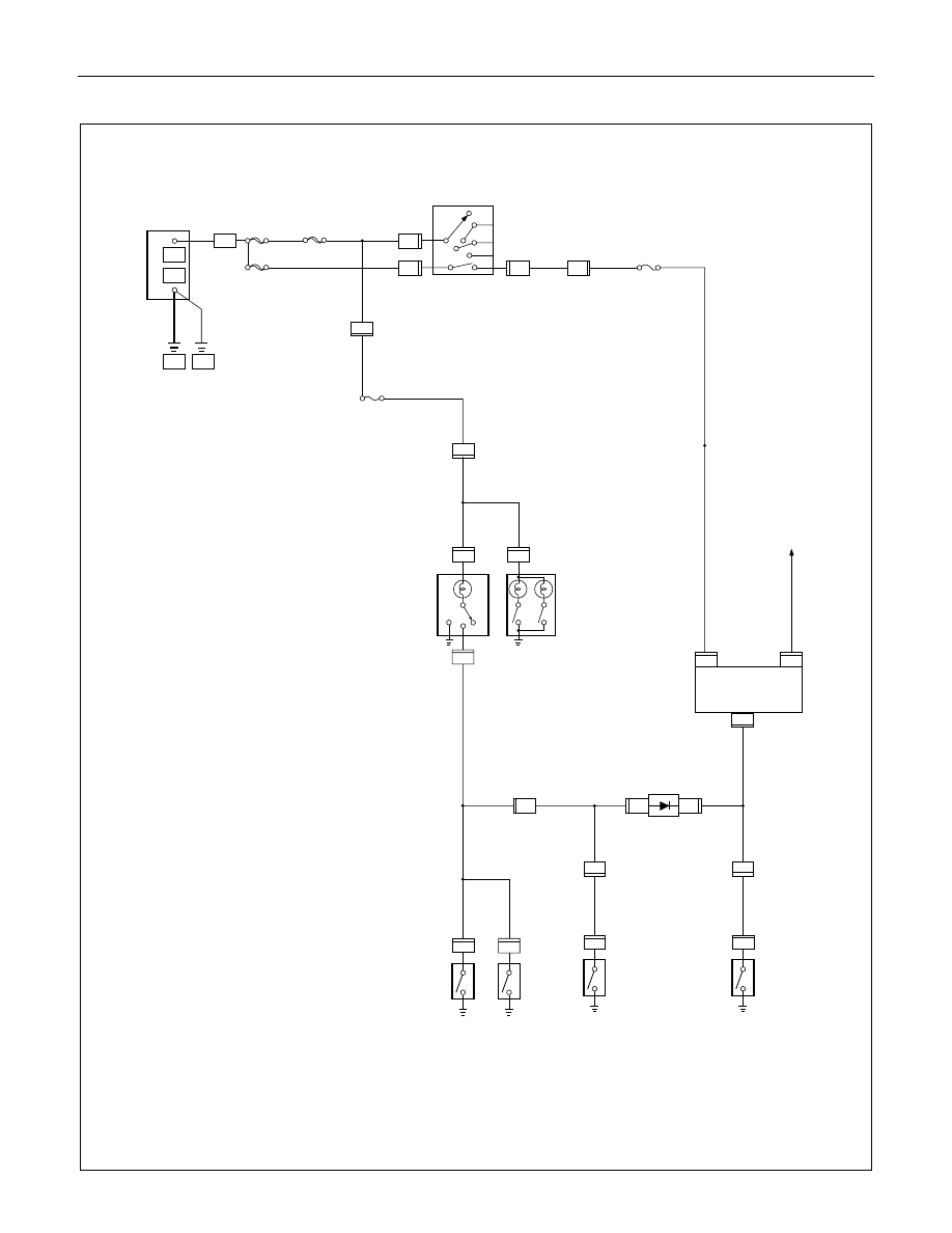
8-172  ELECTRICAL-BODY AND CHASSIS 

CIRCUIT DIAGRAM (EC-LHD) 

H - 9

R - 1

L- 8

P - 1

P - 5

P - 6

8 B

BODY

+

_

P - 10

30B/Y

ENG.

8B/R

P - 2

C - 41

C - 41

ACC

STARTER SW

IG2

ST

IG1

MAIN
80A

1

3

OFF

3 W

C - 41

6

B2

B1

CB-7
15A METER

1

RR DOOR SW-RH

1

RR DOOR SW-LH

L - 1

1

1

OFF

ON

DOOR

DOME LIGHT

H - 11

2

0.85 R/W

H - 11

1

L-2

L - 9

1

MAP LIGHT

0.85 B/W

1

FRT DOOR SW-PASSENGER SIDE

B - 30

3

B - 30

4

DIODE

0.5 R/G

0.85 B/W

0.85 R/G

1

FRT DOOR SW-DRIVER SIDE

B - 5

1

B - 5

B - 5

3

2

LIGHT REMIND BUZZER

0.85 Y

FUSE EB-13

0.85 R/G

0.85 R/G

3 B/R

3 B/R

0.85 B/W

0.85 G/R

3 W/B

3W

0.5R/W

CB-14
10A ROOM LAMP

3W

L- 3

0.85 R/G

0.85 R/G

0.5 R/G

R - 6

13

0.85 B/W

H - 9

12

IGN.B1
40A

0.85 R/W

H - 7

3

IGN.B2
40A

H - 7

2


ELECTRICAL-BODY AND CHASSIS  8-173 

CIRCUIT DIAGRAM (UK) 

H - 9

R - 6

L- 3

P - 1

P - 5

P - 6

8 B

BODY

+

_

P - 10

30B/Y

ENG.

8B/R

P - 2

C - 41

C - 41

ACC

STARTER SW

IG2

ST

IG1

MAIN
100A

1

3

OFF

3 W

C - 41

6

B2

B1

CB-5
15A METER

1

RR DOOR SW-RH

1

RR DOOR SW-LH

L - 1

1

1

OFF

ON

DOOR

DOME LIGHT

H - 11

2

0.85 R/W

0.5 R/W

H - 11

1

L-2

L - 9

1

MAP LIGHT

0.85 R/G

1

FRT DOOR SW-PASSENGER SIDE

B - 30

3

B - 30

4

DIODE

0.5 R/G

0.85 B/W

0.85 B/W

1

FRT DOOR SW-DRIVER SIDE

B - 5

1

B - 5

B - 5

3

2

LIGHT REMIND BUZZER

0.85 Y

RELAY; TAIL (1)

0.85 R/G

0.85 R/G

3 B/R

3 B/R

0.85 B/W

0.85 G/R

3 W/B

3W

CB-14
10A ROOM LAMP

3W

L- 8

0.85 R/G

0.85 R/G

0.5 R/G

R - 1

12

0.85 B/W

H - 9

13

IGN.B1
40A

0.85 R/W

H - 7

5

IGN.B2
40A

H - 7

4


8-174  ELECTRICAL-BODY AND CHASSIS 

TROUBLE SHOOTING 

1.  Dome light dose not light 
 

Checkpoint  

Trouble 

Cause 


Countermeasure 


Replace the dome light bulb

Burned out the bulb

NG

Repair or replace the dome
light assembly

Dome light switch function

Switch malfunction

Repair open circuit or
connector contact

Continuity between
connector 2 

H-11

 - 1 

L-1

Open circuit or poor connector
contact

NG

NG

OK

OK

Dome light bulb continuity


2.  Dome light does not go out 
 

Repair or replace the door
switch

Switch malfunction or foreign
material switch

NG

Repair short circuit or
connector contact

Continuity between
connector 1 

L-2

 -ground

when shutting the door
(Should be no continuity)

Short circuit

NG

OK

Door switch function (Both
side)


ELECTRICAL-BODY AND CHASSIS  8-175 


  REMOVAL AND INSTALLATION 


DOME LIGHT 

Removal 

1.  Remove the dome light lens free. 
2.  Remove three dome light fixing screws. 
3.  Remove the wiring connector. 
4.  Remove the dome light. 


5.  Pull the bulb to remove it. 


Installation 

Follow the removal procedure in the reverse order to install the 
dome light. 
Pay close attention to the important points mentioned in the 
following paragraphs. 


Bulb 

Be absolutely sure that the dome light bulb is correctly 
installed. 
This will prevent a poor contact and an open circuit. 


Content   ..  1206  1207  1208  1209   ..