Infiniti QX4. Electrical System (2003 year). Manual - part 8
 

  Index      Infiniti     Infiniti QX4. Electrical System (2003 year) - manual in english


Search            copyright infringement  


Content      ..     6      7      8      9     ..


Infiniti QX4. Electrical System (2003 year). Manual - part 8


6

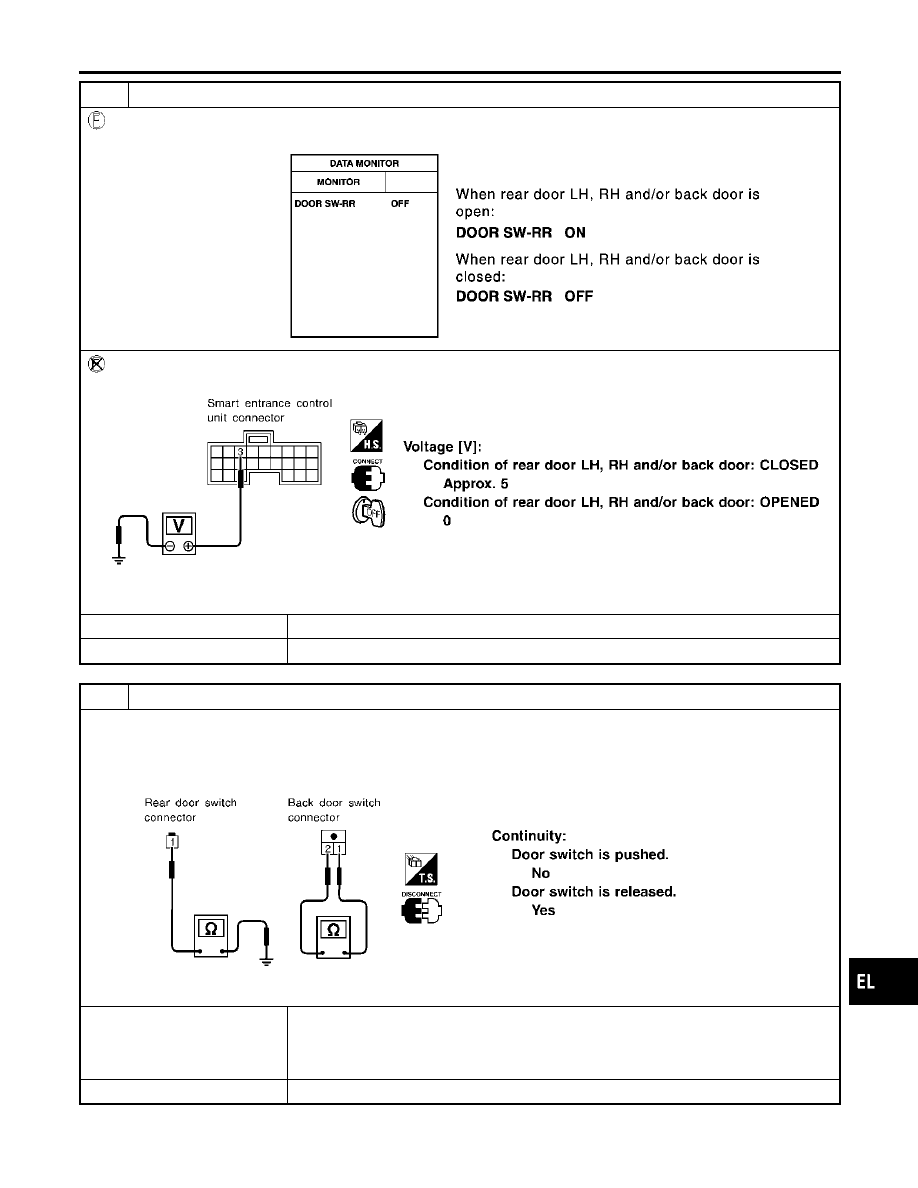
CHECK REAR AND BACK DOOR SWITCHES INPUT SIGNAL

With CONSULT-II

Check door switches (“DOOR SW-RR”) in “DATA MONITOR” mode with CONSULT-II.

SEL154YB

Without CONSULT-II

Check voltage between smart entrance control unit harness connector M121 terminal 3 (R/L) and ground.

SEL155YB

OK or NG

OK

䊳

GO TO 8.

NG

䊳

GO TO 7.

7

CHECK REAR AND BACK DOOR SWITCHES

1. Disconnect door switch harness connector.
2. Check the following.

쐌

Continuity between rear door switches connector B18 and B71 terminal 1 and ground

쐌

Continuity between back door switch connector D208 terminals 1 and 2

SEL279Y

OK or NG

OK

䊳

Check the following.

쐌

Rear LH, RH and/or back door switch ground circuit or door switch ground condition

쐌

Harness for open or short between smart entrance control unit and rear LH, RH and/or
back door switch

NG

䊳

Replace rear LH, RH and/or back door switch.

GI

MA

EM

LC

EC

FE

AT

TF

PD

AX

SU

BR

ST

RS

BT

HA

SC

IDX

INTERIOR, SPOT, VANITY MIRROR AND LUGGAGE ROOM LAMPS

Trouble Diagnoses for Interior Lamp Timer (Cont’d)

EL-117

8

CHECK KEY SWITCH INPUT SIGNAL

With CONSULT-II

Check key switch (“KEY ON SW”) in “DATA MONITOR” mode with CONSULT-II.

SEL315W

Without CONSULT-II

Check voltage between smart entrance control unit harness connector M122 terminal 25 (W/R) and ground.

SEL011Y

OK or NG

OK

䊳

GO TO 10.

NG

䊳

GO TO 9.

9

CHECK KEY SWITCH (INSERT)

Check continuity between terminals 1 and 2.

SEL308X

OK or NG

OK

䊳

Check the following.

쐌

7.5A fuse [No. 24, located in fuse block (J/B)]

쐌

Harness for open or short between key switch and fuse

쐌

Harness for open or short between smart entrance control unit and key switch

NG

䊳

Replace key switch.

INTERIOR, SPOT, VANITY MIRROR AND LUGGAGE ROOM LAMPS

Trouble Diagnoses for Interior Lamp Timer (Cont’d)

EL-118

10

CHECK DOOR LOCK/UNLOCK SWITCH INPUT SIGNAL

With CONSULT-II

Check door lock/unlock switch (“LOCK SW DR/AS”/“UNLK SW DR/AS”) in “DATA MONITOR” mode with CONSULT-II.

SEL341W

Without CONSULT-II

1. Remove key from ignition key cylinder.
2. Check the signal between smart entrance control unit harness connector M122 terminal 33 (BR) and ground with oscil-

loscope when door lock/unlock switch is turned “LOCK” or “UNLOCK”.

3. Make sure signals which are shown in the figure below can be detected during 10 sec. just after door lock/unlock

switch is turned “LOCK” or “UNLOCK”.

SEL699Y

OK or NG

OK

䊳

Door lock/unlock switch is OK.

NG

䊳

Check the following.

쐌

Ground circuit for each front power window switch

쐌

Harness for open or short between each front power window switch and smart
entrance control unit connector

If above systems are normal, replace the front power window switch.

GI

MA

EM

LC

EC

FE

AT

TF

PD

AX

SU

BR

ST

RS

BT

HA

SC

IDX

INTERIOR, SPOT, VANITY MIRROR AND LUGGAGE ROOM LAMPS

Trouble Diagnoses for Interior Lamp Timer (Cont’d)

EL-119

11

CHECK DOOR KEY CYLINDER SWITCH INPUT SIGNAL (LOCK/UNLOCK SIGNAL)

With CONSULT-II

Check front door key cylinder switch (“KEY CYL LK-SW”/“KEY CYL UN-SW”) in “DATA MONITOR” mode with CONSULT-
II.

SEL342W

Without CONSULT-II

1. Check the signal between smart entrance control unit harness connector M122 terminal 33 (BR) and ground with oscil-

loscope when key inserted in front key cylinder is turned “LOCK” or “UNLOCK”.

2. Make sure signals which are shown in the figure below can be detected during 10 sec. just after key is turned “LOCK”

or “UNLOCK”.

SEL700Y

OK or NG

OK

䊳

Door key cylinder switch LH is OK.

NG

䊳

GO TO 12.

12

CHECK FRONT DOOR KEY CYLINDER SWITCH INPUT SIGNAL (LOCK/UNLOCK SIGNAL)

Check voltage between power window main switch harness connector D6 terminals 4 (Y/L) or 6 (LG) and ground.

SEL792Y

OK or NG

OK

䊳

Replace smart entrance control unit.

NG

䊳

GO TO 13.

INTERIOR, SPOT, VANITY MIRROR AND LUGGAGE ROOM LAMPS

Trouble Diagnoses for Interior Lamp Timer (Cont’d)

EL-120

13

CHECK BACK DOOR KEY CYLINDER SWITCH INPUT SIGNAL (LOCK/UNLOCK SIGNAL)

With CONSULT-II

Check back door key cylinder switch (“KEY CYL LK-SW”/“KEY CYL UN-SW”) in “DATA MONITOR” mode with CONSULT-
II.

SEL342WB

Without CONSULT-II

Check voltage between smart entrance control unit harness connector M121 terminals 10 (LG), 11 (Y) and ground.

SEL680Y

OK or NG

OK

䊳

Replace smart entrance control unit.

NG

䊳

GO TO 14.

GI

MA

EM

LC

EC

FE

AT

TF

PD

AX

SU

BR

ST

RS

BT

HA

SC

IDX

INTERIOR, SPOT, VANITY MIRROR AND LUGGAGE ROOM LAMPS

Trouble Diagnoses for Interior Lamp Timer (Cont’d)

EL-121

14

CHECK DOOR KEY CYLINDER SWITCH

1. Disconnect door key cylinder switch harness connector.
2. Check continuity between each key cylinder switch terminals.

쐌

Front door key cylinder switch LH harness connector D9

SEL793Y

쐌

Back door key cylinder switch harness connector D201

SEL315X

OK or NG

OK

䊳

Check the following.

쐌

Front or back door key cylinder switch ground circuit

쐌

Harness for open or short between back door key cylinder switch and smart entrance
control unit connector

쐌

Harness for open or short between front door key cylinder switch LH and power win-
dow main switch

NG

䊳

Replace front or back door key cylinder switch.

INTERIOR, SPOT, VANITY MIRROR AND LUGGAGE ROOM LAMPS

Trouble Diagnoses for Interior Lamp Timer (Cont’d)

EL-122

DIAGNOSTIC PROCEDURE 2

=NBEL0489S02

SYMPTOM: Interior lamp timer does not cancel properly.

1

CHECK IGNITION ON SIGNAL

With CONSULT-II

Check ignition switch ON signal (“IGN ON SW”) in “DATA MONITOR” mode with CONSULT-II.

SEL318W

Without CONSULT-II

Check voltage between smart entrance control unit harness connector M122 terminal 27 (W/B) and ground.

SEL995X

OK or NG

OK

䊳

GO TO 2.

NG

䊳

Check the following.

쐌

7.5A fuse [No. 11, located in fuse block (J/B)]

쐌

Harness for open or short between smart entrance control unit and fuse

GI

MA

EM

LC

EC

FE

AT

TF

PD

AX

SU

BR

ST

RS

BT

HA

SC

IDX

INTERIOR, SPOT, VANITY MIRROR AND LUGGAGE ROOM LAMPS

Trouble Diagnoses for Interior Lamp Timer (Cont’d)

EL-123

2

CHECK FRONT DOOR SWITCH LH INPUT SIGNAL

With CONSULT-II

Check driver door switch signal (“DOOR SW-DR”) in “DATA MONITOR” mode with CONSULT-II.

SEL319WB

Without CONSULT-II

Check voltage between smart entrance control unit harness connector M121 terminal 1 (G/OR) and ground.

SEL004YD

OK or NG

OK

䊳

GO TO 4.

NG

䊳

GO TO 3.

3

CHECK FRONT DOOR SWITCH LH

Check the following.

쐌

Continuity between front door switch LH connector B9 terminals 1 and 2

쐌

Continuity between front door switch LH connector B9 terminal 3 and ground

SEL277Y

OK or NG

OK

䊳

Check the following.

쐌

Front door switch LH ground circuit and condition

쐌

Harness for open or short between smart entrance control unit and front door switch
LH

NG

䊳

Replace front door switch LH.

INTERIOR, SPOT, VANITY MIRROR AND LUGGAGE ROOM LAMPS

Trouble Diagnoses for Interior Lamp Timer (Cont’d)

EL-124

4

CHECK DOOR LOCK/UNLOCK SWITCH INPUT SIGNAL

With CONSULT-II

Check door lock/unlock switch (“LOCK SW DR/AS”/“UNLK SW DR/AS”) in “DATA MONITOR” mode with CONSULT-II.

SEL341W

Without CONSULT-II

1. Remove key from ignition key cylinder.
2. Check the signal between smart entrance control unit harness connector M122 terminal 33 (BR) and ground with oscil-

loscope when door lock/unlock switch is turned “LOCK” or “UNLOCK”.

3. Make sure signals which are shown in the figure below can be detected during 10 sec. just after door lock/unlock

switch is turned “LOCK” or “UNLOCK”.

SEL699Y

OK or NG

OK

䊳

Door lock/unlock switch is OK.

NG

䊳

Check the following.

쐌

Ground circuit for each front power window switch

쐌

Harness for open or short between each front power window switch and smart
entrance control unit connector

If above systems are normal, replace the front power window switch.

GI

MA

EM

LC

EC

FE

AT

TF

PD

AX

SU

BR

ST

RS

BT

HA

SC

IDX

INTERIOR, SPOT, VANITY MIRROR AND LUGGAGE ROOM LAMPS

Trouble Diagnoses for Interior Lamp Timer (Cont’d)

EL-125

5

CHECK DOOR KEY CYLINDER SWITCH INPUT SIGNAL (LOCK/UNLOCK SIGNAL)

With CONSULT-II

Check front door key cylinder switch (“KEY CYL LK-SW”/“KEY CYL UN-SW”) in “DATA MONITOR” mode with CONSULT-
II.

SEL792Y

Without CONSULT-II

1. Check the signal between smart entrance control unit harness connector M122 terminal 33 (BR) and ground with oscil-

loscope when key inserted in front key cylinder is turned “LOCK” or “UNLOCK”.

2. Make sure signals which are shown in the figure below can be detected during 10 sec. just after key is turned “LOCK”

or “UNLOCK”.

SEL700Y

OK or NG

OK

䊳

Door key cylinder switch LH is OK.

NG

䊳

GO TO 6.

6

CHECK FRONT DOOR KEY CYLINDER SWITCH INPUT SIGNAL (LOCK/UNLOCK SIGNAL)

Check voltage between power window main switch harness connector D6 terminals 4 (Y/L) or 6 (LG) and ground.

SEL792Y

OK or NG

OK

䊳

Replace smart entrance control unit.

NG

䊳

GO TO 7.

INTERIOR, SPOT, VANITY MIRROR AND LUGGAGE ROOM LAMPS

Trouble Diagnoses for Interior Lamp Timer (Cont’d)

EL-126

7

CHECK BACK DOOR KEY CYLINDER SWITCH INPUT SIGNAL (LOCK/UNLOCK SIGNAL)

With CONSULT-II

Check back door key cylinder switch (“KEY CYL LK-SW”/“KEY CYL UN-SW”) in “DATA MONITOR” mode with CONSULT-
II.

SEL342WB

Without CONSULT-II

Check voltage between smart entrance control unit harness connector M121 terminals 10 (LG), 11 (Y) and ground.

SEL680Y

OK or NG

OK

䊳

Replace smart entrance control unit.

NG

䊳

GO TO 8.

GI

MA

EM

LC

EC

FE

AT

TF

PD

AX

SU

BR

ST

RS

BT

HA

SC

IDX

INTERIOR, SPOT, VANITY MIRROR AND LUGGAGE ROOM LAMPS

Trouble Diagnoses for Interior Lamp Timer (Cont’d)

EL-127

8

CHECK DOOR KEY CYLINDER SWITCH

1. Disconnect door key cylinder switch harness connector.
2. Check continuity between each key cylinder switch terminals.

쐌

Front door key cylinder switch harness connector D9

SEL793Y

쐌

Back door key cylinder switch harness connector D201

SEL315X

OK or NG

OK

䊳

Check the following.

쐌

Front or back door key cylinder switch ground circuit

쐌

Harness for open or short between back door key cylinder switch and smart entrance
control unit connector

쐌

Harness for open or short between front door key cylinder switch and power window
main switch

NG

䊳

Replace front or back door key cylinder switch.

INTERIOR, SPOT, VANITY MIRROR AND LUGGAGE ROOM LAMPS

Trouble Diagnoses for Interior Lamp Timer (Cont’d)

EL-128

Component Parts and Harness Connector
Location

NBEL0296

SEL799Y

System Description

NBEL0297

UNIFIED CONTROL METER

NBEL0297S01

쐌

Speedometer, odo/trip meter, tachometer, fuel gauge and water temperature gauge are controlled totally
by control unit.

쐌

Digital meter is adopted for odo/trip meter.*
*The record of the odo meter is kept even if the battery cable is disconnected. The record of the trip meter
is erased when the battery cable is disconnected.

쐌

Odo/trip meter segment can be checked in diagnosis mode.

쐌

Meter/gauge can be checked in diagnosis mode.

HOW TO CHANGE THE DISPLAY FOR ODO/TRIP METER

NBEL0297S02

SEL175W

NOTE:
Turn ignition switch to the “ON” position to operate odo/trip meter.

GI

MA

EM

LC

EC

FE

AT

TF

PD

AX

SU

BR

ST

RS

BT

HA

SC

IDX

METERS AND GAUGES

Component Parts and Harness Connector Location

EL-129

POWER SUPPLY AND GROUND CIRCUIT

NBEL0297S03

Power is supplied at all times

쐌

through 7.5A fuse [No. 24, located in the fuse block (J/B)]

쐌

to combination meter terminal 62.

With the ignition switch in the ON or START position, power is supplied

쐌

through 10A fuse [No. 8, located in the fuse block (J/B)]

쐌

to combination meter terminal 66.

With ignition switch in the ACC or ON position, power is supplied

쐌

through 10A fuse [No. 9, located in the fuse block (J/B)]

쐌

to combination meter terminal 31.

Ground is supplied

쐌

to combination meter terminal 59

쐌

through body grounds M4, M66 and M147.

WATER TEMPERATURE GAUGE

NBEL0297S04

The water temperature gauge indicates the engine coolant temperature. The reading on the gauge is based
on the resistance of the thermal transmitter.
As the temperature of the coolant increases, the resistance of the thermal transmitter decreases. A variable
ground is supplied to terminal 18 of the combination meter for the water temperature gauge. The needle on
the gauge moves from “C” to “H”.

TACHOMETER

NBEL0297S05

The tachometer indicates engine speed in revolutions per minute (rpm).
The tachometer is regulated by a signal

쐌

from terminal 25 of the ECM

쐌

to combination meter terminal 16 for the tachometer.

FUEL GAUGE

NBEL0297S06

The fuel gauge indicates the approximate fuel level in the fuel tank.
The fuel gauge is regulated by a variable ground signal supplied

쐌

to combination meter terminal 17 for the fuel gauge

쐌

from terminal 3 of the fuel level sensor unit

쐌

through terminal 2 of the fuel level sensor unit and

쐌

through body grounds B11, B22 and D210.

SPEEDOMETER

NBEL0297S07

The ABS actuator and electric unit provides a voltage signal to the combination meter for the speedometer.
The voltage is supplied

쐌

from combination meter terminal 15 for the speedometer

쐌

to terminal 19 of the ABS actuator and electric unit.

The speedometer converts the voltage into the vehicle speed displayed.

METERS AND GAUGES

System Description (Cont’d)

EL-130

Combination Meter

NBEL0298

CHECK

NBEL0298S01

MEL388Q

GI

MA

EM

LC

EC

FE

AT

TF

PD

AX

SU

BR

ST

RS

BT

HA

SC

IDX

METERS AND GAUGES

Combination Meter

EL-131

CONSTRUCTION

NBEL0298S02

SEL644W

METERS AND GAUGES

Combination Meter (Cont’d)

EL-132


Content      ..     6      7      8      9     ..