Infiniti I30. Emission Control System (2003 year). Manual - part 28


  Index      Infiniti     Infiniti I30. Emission Control System (2003 year) - manual in english


Search            copyright infringement  


Content      ..     26      27      28      29     ..


Infiniti I30. Emission Control System (2003 year). Manual - part 28


2

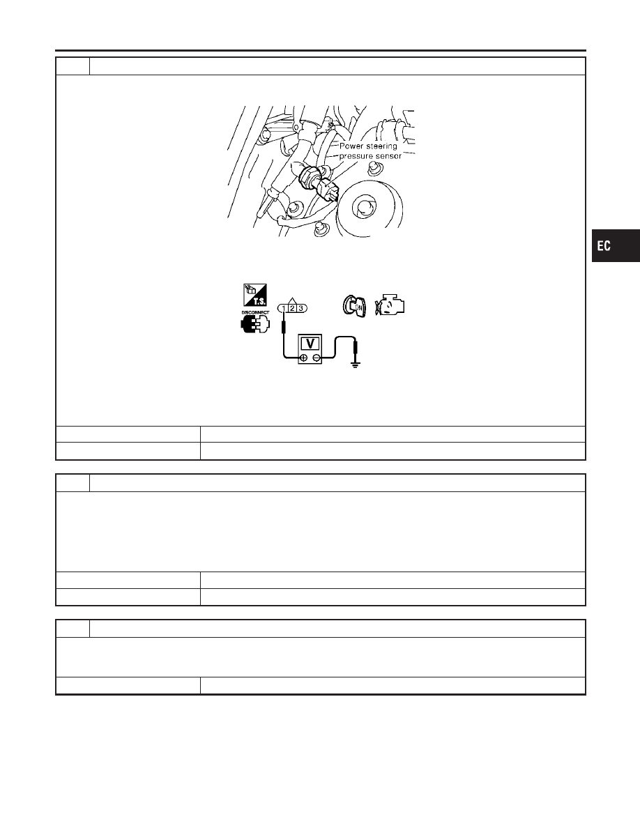
CHECK PSP SENSOR POWER SUPPLY CIRCUIT

1. Disconnect PSP sensor harness connector.
2. Turn ignition switch “ON”.

SEC046D

3. Check voltage between PSP sensor terminal 1 and ground with CONSULT-II or tester.

SEC048D

Voltage: Approximately 5V

OK or NG

OK

GO TO 3.

NG

Repair harness or connectors.

3

CHECK PSP SENSOR GROUND CIRCUIT FOR OPEN AND SHORT

1. Turn ignition switch “OFF”.
2. Check harness continuity between PSP sensor terminal 3 and engine ground.

Refer to Wiring Diagram.

Continuity should exist.

3. Also check harness for short to power.

OK or NG

OK

GO TO 5.

NG

GO TO 4.

4

DETECT MALFUNCTIONING PART

Check the following.

Harness for open or short between ECM and PSP sensor

Harness for open or short between TCM (Transmission Control Module) and PSP sensor.

Repair open circuit or short to ground or short to power in harness or connectors.

GI

MA

EM

LC

FE

AT

AX

SU

BR

ST

RS

BT

HA

SC

EL

IDX

DTC P0550 PSP SENSOR

Diagnostic Procedure (Cont’d)

EC-433

5

CHECK PSP SENSOR INPUT SIGNAL CIRCUIT FOR OPEN AND SHORT

1. Disconnect ECM harness connector.
2. Check harness continuity between ECM terminal 89 and PSP sensor terminal 2.

Continuity should exist.

3. Also check harness for short to ground and short to power.

OK or NG

OK

GO TO 6.

NG

Repair open circuit or short to ground or short to power in harness or connectors.

6

CHECK PSP SENSOR

Refer to “Component Inspection”, EC-434.

OK or NG

OK

GO TO 7.

NG

Replace PSP sensor.

7

CHECK INTERMITTENT INCIDENT

Refer to “TROUBLE DIAGNOSIS FOR INTERMITTENT INCIDENT”, EC-151.

INSPECTION END

SEC049D

Component Inspection

NHEC1257

POWER STEERING PRESSURE SENSOR
1.

Reconnect all harness connectors disconnected.

2.

Start engine and let it idle.

3.

Check voltage between ECM terminal 89 and ground under
the following conditions.

Condition

Voltage

Steering wheel is turned fully.

Approximately 0.5 - 4.0V

Steering wheel is not turned.

Approximately 0.4 - 0.8V

DTC P0550 PSP SENSOR

Diagnostic Procedure (Cont’d)

EC-434

SEF093X

Component Description

NHEC1032

The ECM consists of a microcomputer and connectors for signal
input and output and for power supply. The unit controls the engine.

On Board Diagnosis Logic

NHEC1033

This self-diagnosis has one or two trip detection logic.

DTC No.

Trouble diagnosis

name

DTC Detecting Condition

Possible Cause

P0605
0605

Engine control module

A)

ECM calculation function is malfunctioning.

ECM

B)

ECM EEP-ROM system is malfunctioning.

C)

ECM self shut-off function is malfunctioning.

FAIL-SAFE MODE

Detected items

Engine operation condition in fail-safe mode

Malfunction A

ECM stops the electric throttle control actuator control, throttle valve is maintained at a fixed opening
(approx. 5 degrees) by the return spring.

ECM deactivates ASCD operation.

DTC Confirmation Procedure

NHEC1445

Perform “PROCEDURE FOR MALFUNCTION A” first. If the 1st
trip DTC cannot be confirmed, perform “PROCEDURE FOR
MALFUNCTION B”. If there is no malfunction on “PROCE-
DURE FOR MALFUNCTION B”, perform “PROCEDURE FOR
MALFUNCTION C”.
NOTE:
If “DTC Confirmation Procedure” has been previously conducted,
always turn ignition switch “OFF” and wait at least 10 seconds
before conducting the next test.

SEF058Y

PROCEDURE FOR MALFUNCTION A

With CONSULT-II

1)

Turn ignition switch “ON”.

2)

Select “DATA MONITOR” mode with CONSULT-II.

3)

If 1st trip DTC is detected, go to EC-436, “Diagnostic Proce-
dure”.

With GST

Follow the procedure “With CONSULT-II” above.

GI

MA

EM

LC

FE

AT

AX

SU

BR

ST

RS

BT

HA

SC

EL

IDX

DTC P0605 ECM

Component Description

EC-435

SEF058Y

PROCEDURE FOR MALFUNCTION B

With CONSULT-II

1)

Turn ignition switch “ON” and wait at least 1 second.

2)

Select “DATA MONITOR” mode with CONSULT-II.

3)

Turn ignition switch “OFF”, wait at least 10 seconds, and then
turn “ON”.

4)

If 1st trip DTC is detected, go to EC-436, “Diagnostic Proce-
dure”.

With GST

Follow the procedure “With CONSULT-II” above.

SEF058Y

PROCEDURE FOR MALFUNCTION C

With CONSULT-II

1)

Turn ignition switch “ON” and wait at least 1 second.

2)

Select “DATA MONITOR” mode with CONSULT-II.

3)

Turn ignition switch “OFF”, wait at least 10 seconds, and then
turn “ON”.

4)

Repeat step 3 procedure, 32 times.

5)

If 1st trip DTC is detected, go to EC-436, “Diagnostic Proce-
dure”.

With GST

Follow the procedure “With CONSULT-II” above.

Diagnostic Procedure

NHEC1035

1

INSPECTION START

With CONSULT-II

1. Turn ignition switch “ON”.
2. Select “SELF DIAG RESULTS” mode with CONSULT-II.
3. Touch “ERASE”.
4. Perform “DTC Confirmation Procedure”.

See EC-435.

5. Is the 1st trip DTC P0605 displayed again?

With GST

1. Turn ignition switch “ON”.
2. Select MODE 4 with GST.
3. Touch “ERASE”.
4. Perform “DTC Confirmation Procedure”.

See EC-435.

5. Is the 1st trip DTC P0605 displayed again?

Yes or No

Yes

GO TO 2.

No

INSPECTION END

2

REPLACE ECM

1. Replace ECM.
2. Perform initialization of IVIS (NATS) system and registration of all IVIS (NATS) ignition key IDs. Refer to “IVIS (INFINITI

VEHICLE IMMOBILIZER SYSTEM — NATS)”, EC-90.

3. Perform “Accelerator Pedal Released Position Learning”, EC-71.
4. Perform “Throttle Valve Closed Position Learning”, EC-71.
5. Perform “Idle Air Volume Learning”, EC-71.

INSPECTION END

DTC P0605 ECM

DTC Confirmation Procedure (Cont’d)

EC-436

Component Description

NHEC1258

Malfunction Indicator Lamp (MIL) is located on the instrument panel. When the ignition switch is turned ON
without engine running, MIL will light up. This is a bulb check. When the engine is started, MIL should go off.
If MIL remains on, the on board diagnostic system has detected an engine system malfunction.

On Board Diagnosis Logic

NHEC1259

The MIL will not light up for this self-diagnosis.

DTC No.

Trouble diagnosis name

DTC detecting condition

Possible cause

P0650
0650

Malfunction indicator
(MIL) control circuit

An excessively high voltage is sent to ECM
through the MIL circuit under the condition
that calls for MIL light up.

An excessively low voltage is sent to ECM
through the MIL circuit under the condition
that calls for MIL not to light up.

Harness or connectors
(MIL circuit is open or shorted.)

MIL

FAIL-SAFE MODE
ECM enters fail-safe mode when both DTC P0650 and another DTC, which calls for MIL to light up, are
detected at the same time.

Detected items

Engine operating condition in fail-safe mode

MIL circuit

Engine speed will not rise more than 2,500 rpm due to the fuel cut.

DTC Confirmation Procedure

NHEC1260

NOTE:
If “DTC Confirmation Procedure” has been previously conducted,
always turn ignition switch “OFF” and wait at least 10 seconds
before conducting the next test.

SEF058Y

With CONSULT-II

1.

Turn ignition switch “ON” and wait at least 1 second.

2.

Select “DATA MONITOR” mode with CONSULT-II.

3.

Start engine and let it idle for 1 second.

4.

If 1st trip DTC is detected, go to “Diagnostic Procedure”,
EC-439.

WITH GST

Follow the procedure “WITH CONSULT-II” above.

GI

MA

EM

LC

FE

AT

AX

SU

BR

ST

RS

BT

HA

SC

EL

IDX

DTC P0650 MIL (CIRCUIT)

Component Description

EC-437

Wiring Diagram

NHEC1261

MEC572D

DTC P0650 MIL (CIRCUIT)

Wiring Diagram

EC-438

Specification data are reference values and are measured between each terminal and body ground.

CAUTION:

Do not use ECM ground terminals when measuring input/output voltage. Doing so may result in dam-
age to the ECM’s transistor. Use a ground other than ECM terminals, such as the ground.

TER-

MINAL

NO.

WIRE

COLOR

ITEM

CONDITION

DATA (DC Voltage)

33

LG/B

MIL

[Ignition switch “ON”]

0 - 1.0V

[Engine is running]

Idle speed

BATTERY VOLTAGE
(11 - 14V)

Diagnostic Procedure

NHEC1262

1

CHECK MIL POWER SUPPLY CIRCUIT

1. Turn ignition switch “OFF”.
2. Disconnect combination meter harness connector.
3. Turn ignition switch “ON”.
4. Check voltage between combination meter terminal 24 and ground with CONSULT-II or tester.

SEC050D

Voltage: Battery voltage

OK or NG

OK

GO TO 3.

NG

GO TO 2.

2

DETECT MALFUNCTIONING PART

Check the following.

Fuse block (J/B) connector M19

10A fuse

Harness for open or short between fuse block (J/B) and combination meter

Repair harness or connectors.

3

CHECK MIL OUTPUT SIGNAL CIRCUIT FOR OPEN AND SHORT

1. Turn ignition switch “OFF”.
2. Disconnect ECM harness connector.
3. Check harness continuity between ECM terminal 33 and combination meter terminal 45.

Refer to Wiring Diagram.

Continuity should exist.

4. Also check harness for short to ground and short to power.

OK or NG

OK

GO TO 5.

NG

GO TO 4.

GI

MA

EM

LC

FE

AT

AX

SU

BR

ST

RS

BT

HA

SC

EL

IDX

DTC P0650 MIL (CIRCUIT)

Wiring Diagram (Cont’d)

EC-439

4

DETECT MALFUNCTIONING PART

Check the following.

Harness connectors M229, F66

Harness for open or short between ECM and combination meter

Repair open circuit or short to ground or short to power in harness or connectors.

5

CHECK INTERMITTENT INCIDENT

Refer to “TROUBLE DIAGNOSIS FOR INTERMITTENT INCIDENT”, EC-151.

OK or NG

OK

Replace combination meter. Refer to EL-125, “METERS AND GAUGES”.

NG

Repair or replace.

DTC P0650 MIL (CIRCUIT)

Diagnostic Procedure (Cont’d)

EC-440

SEF093X

Component Description

NHEC1263

Battery voltage is supplied to the ECM even when the ignition
switch is turned OFF for the ECM memory function of the DTC
memory, the air fuel ratio feedback compensation value memory,
the idle air volume learning value memory, etc.

On Board Diagnosis Logic

NHEC1264

DTC No.

Trouble diagnosis name

DTC detecting condition

Possible cause

P1065
1065

ECM power supply cir-
cuit

ECM back-up RAM system does not function
properly.

Harness or connectors
[ECM power supply (back-up) circuit
is open or shorted.]

ECM

DTC Confirmation Procedure

NHEC1265

NOTE:
If “DTC Confirmation Procedure” has been previously conducted,
always turn ignition switch “OFF” and wait at least 10 seconds
before conducting the next test.

SEF058Y

With CONSULT-II

1.

Turn ignition switch “ON” and wait at least 1 second.

2.

Select “DATA MONITOR” mode with CONSULT-II.

3.

Start engine and let it idle for 1 second.

4.

Turn ignition switch “OFF”, wait at least 10 seconds, and then
turn “ON”.

5.

Repeat steps 3 and 4 four times.

6.

If 1st trip DTC is detected, go to “Diagnostic Procedure”,
EC-443.

With GST

Follow the procedure “WITH CONSULT-II” above.

GI

MA

EM

LC

FE

AT

AX

SU

BR

ST

RS

BT

HA

SC

EL

IDX

DTC P1065 ECM POWER SUPPLY (BACK UP)

Component Description

EC-441

Wiring Diagram

NHEC1266

MEC703D

DTC P1065 ECM POWER SUPPLY (BACK UP)

Wiring Diagram

EC-442

Specification data are reference values and are measured between each terminal and body ground.

CAUTION:

Do not use ECM ground terminals when measuring input/output voltage. Doing so may result in dam-
age to the ECM’s transistor. Use a ground other than ECM terminals, such as the ground.

TER-

MINAL

NO.

WIRE

COLOR

ITEM

CONDITION

DATA (DC Voltage)

67

W/L

Power supply for ECM
(Back-up)

[Ignition switch “OFF”]

BATTERY VOLTAGE
(11 - 14V)

Diagnostic Procedure

NHEC1267

1

CHECK ECM POWER SUPPLY

1. Turn ignition switch “OFF”.
2. Disconnect ECM harness connector.
3. Check voltage between ECM terminal 67 and ground with CONSULT-II or tester.

SEC912C

Voltage: Battery voltage

OK or NG

OK

GO TO 3.

NG

GO TO 2.

2

DETECT MALFUNCTIONING PART

Check the following.

Harness connectors E15, F18

Joint connector-13

15A fuse

Harness for open or short between ECM and fuse

Repair or replace harness or connectors.

3

CHECK INTERMITTENT INCIDENT

Refer to “TROUBLE DIAGNOSIS FOR INTERMITTENT INCIDENT”, EC-151.

OK or NG

OK

GO TO 4.

NG

Repair or replace harness or connectors.

GI

MA

EM

LC

FE

AT

AX

SU

BR

ST

RS

BT

HA

SC

EL

IDX

DTC P1065 ECM POWER SUPPLY (BACK UP)

Wiring Diagram (Cont’d)

EC-443

4

PERFORM DTC CONFIRMATION PROCEDURE

With CONSULT-II

1. Turn ignition switch “ON”.
2. Select “SELF DIAG RESULTS” mode with CONSULT-II.
3. Touch “ERASE”.
4. Perform “DTC Confirmation Procedure”.

See EC-441.

5. Is the 1st trip DTC P1065 displayed again?

With GST

1. Turn ignition switch “ON”.
2. Select MODE 4 with GST.
3. Touch “ERASE”.
4. Perform “DTC Confirmation Procedure”.

See EC-441.

5. Is the 1st trip DTC P1065 displayed again?

Yes or No

Yes

GO TO 5.

No

INSPECTION END

5

REPLACE ECM

1. Replace ECM.
2. Perform initialization of IVIS (NATS) system and registration of all IVIS (NATS) ignition key IDs. Refer to “IVIS (INFINITI

VEHICLE IMMOBILIZER SYSTEM — NATS)”, EC-90.

3. Perform “Accelerator Pedal Released Position Learning”, EC-71.
4. Perform “Throttle Valve Closed Position Learning”, EC-71.
5. Perform “Idle Air Volume Learning”, EC-71.

INSPECTION END

DTC P1065 ECM POWER SUPPLY (BACK UP)

Diagnostic Procedure (Cont’d)

EC-444

SEC266C

Component Description

NHEC0803

The mass air flow sensor is placed in the stream of intake air. It
measures the intake flow rate by measuring a part of the entire
intake flow. It consists of a hot film that is supplied with electric
current from the ECM. The temperature of the hot film is controlled
by the ECM a certain amount. The heat generated by the hot film
is reduced as the intake air flows around it. The more air, the
greater the heat loss.
Therefore, the ECM must supply more electric current to maintain
the temperature of the hot film as air flow increases. The ECM
detects the air flow by means of this current change.

CONSULT-II Reference Value in Data Monitor
Mode

NHEC0804

Specification data are reference values.

MONITOR ITEM

CONDITION

SPECIFICATION

MAS A/F SE-B1

Engine: After warming up

Air conditioner switch: “OFF”

Shift lever: “N”

No-load

Idle

1.1 - 1.5V

2,500 rpm

1.7 - 2.4V

CAL/LD VALUE

ditto

Idle

10 - 35%

2,500 rpm

10 - 35%

MASS AIRFLOW

ditto

Idle

2.0 - 6.0 g·m/s

2,500 rpm

7.0 - 20.0 g·m/s

On Board Diagnosis Logic

NHEC1446

This self-diagnosis has the one trip detection logic.

DTC No.

Trouble diagnosis

name

DTC Detecting Condition

Possible Cause

P1102
1102

Mass air flow sensor
circuit range/
performance problem

A voltage from the sensor is constantly approx.
1.0V when engine is running.

Harness or connectors
(The sensor circuit is open or
shorted.)

Mass air flow sensor

FAIL-SAFE MODE

NHEC1446S01

When the malfunction is detected, the ECM enters fail-safe mode and the MIL lights up.

Detected items

Engine operating condition in fail-safe mode

Mass air flow sensor circuit

Engine speed will not rise more than 2,400 rpm due to the fuel cut.

DTC Confirmation Procedure

NHEC1447

NOTE:
If “DTC Confirmation Procedure” has been previously conducted,
always turn ignition switch “OFF” and wait at least 10 seconds
before conducting the next test.

GI

MA

EM

LC

FE

AT

AX

SU

BR

ST

RS

BT

HA

SC

EL

IDX

DTC P1102 MAF SENSOR

Component Description

EC-445

SEF058Y

WITH CONSULT-II

NHEC1447S01

1)

Turn ignition switch “ON”.

2)

Select “DATA MONITOR” mode with CONSULT-II.

3)

Start engine and wait at least 5 seconds.

4)

If DTC is detected, go to “Diagnostic Procedure”, EC-448.

WITH GST

NHEC1447S02

Follow the procedure “With CONSULT-II” above.

DTC P1102 MAF SENSOR

DTC Confirmation Procedure (Cont’d)

EC-446

Wiring Diagram

=NHEC0810

MEC531D

SEF650XE

GI

MA

EM

LC

FE

AT

AX

SU

BR

ST

RS

BT

HA

SC

EL

IDX

DTC P1102 MAF SENSOR

Wiring Diagram

EC-447

Diagnostic Procedure

=NHEC0811

1

CHECK INTAKE SYSTEM

Check the following for connection.

Air duct

Vacuum hoses

OK or NG

OK

GO TO 2.

NG

Reconnect the parts.

2

RETIGHTEN GROUND SCREWS

1. Turn ignition switch “OFF”.
2. Loosen and retighten engine ground screws.

SEC047D

GO TO 3.

DTC P1102 MAF SENSOR

Diagnostic Procedure

EC-448


Content      ..     26      27      28      29     ..