Infiniti I30. Emission Control System (2003 year). Manual - part 16


  Index      Infiniti     Infiniti I30. Emission Control System (2003 year) - manual in english


Search            copyright infringement  


Content      ..     14      15      16      17     ..


Infiniti I30. Emission Control System (2003 year). Manual - part 16


SEF463R

SEF288D

Component Description

NHEC0888

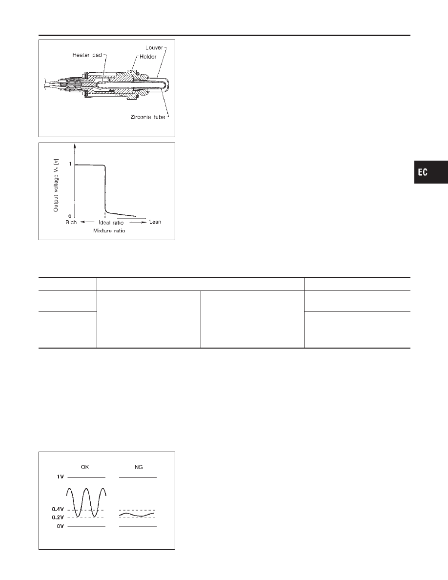
The heated oxygen sensor 1 is placed into the front tube. It detects
the amount of oxygen in the exhaust gas compared to the outside
air. The heated oxygen sensor 1 has a closed-end tube made of
ceramic zirconia. The zirconia generates voltage from approxi-
mately 1V in richer conditions to 0V in leaner conditions. The
heated oxygen sensor 1 signal is sent to the ECM. The ECM
adjusts the injection pulse duration to achieve the ideal air-fuel
ratio. The ideal air-fuel ratio occurs near the radical change from
1V to 0V.

CONSULT-II Reference Value in Data Monitor
Mode

NHEC0889

Specification data are reference values.

MONITOR ITEM

CONDITION

SPECIFICATION

HO2S1 (B1)
HO2S1 (B2)

Engine: After warming up

Maintaining engine speed at 2,000
rpm

0 - 0.3V

+,

Approx. 0.6 - 1.0V

HO2S1 MNTR
(B1)
HO2S1 MNTR
(B2)

LEAN

+,

RICH

Changes more than 5 times during
10 seconds.

SEF237U

On Board Diagnosis Logic

NHEC0891

Under the condition in which the heated oxygen sensor 1 signal is
not input, the ECM circuits will read a continuous approximately
0.3V. Therefore, for this diagnosis, the time that output voltage is
within 200 to 400 mV range is monitored, and the diagnosis checks
that this time is not inordinately long.

GI

MA

EM

LC

FE

AT

AX

SU

BR

ST

RS

BT

HA

SC

EL

IDX

DTC P0134, P0154 HO2S1

Component Description

EC-241

DTC No.

Trouble diagnosis

name

DTC Detecting Condition

Possible Cause

P0134
0134
(Bank 1)
P0154
0154
(Bank 2)

Heated oxygen sen-
sor 1 circuit no activ-
ity detected

The voltage from the sensor is constantly approx.
0.3V.

Harness or connectors
(The sensor circuit is open or
shorted.)

Heated oxygen sensor 1

PBIB0544E

PBIB0545E

SEC750C

DTC Confirmation Procedure

NHEC1433

CAUTION:

Always drive vehicle at a safe speed.
NOTE:
If “DTC Confirmation Procedure” has been previously conducted,
always turn ignition switch “OFF” and wait at least 10 seconds
before conducting the next test.
TESTING CONDITION:
Before performing the following procedure, confirm that bat-
tery voltage is more than 11V at idle.

WITH CONSULT-II

NHEC1433S01

1)

Start engine and warm it up to normal operating temperature.

2)

Select “HO2S1 (B1)/(B2) P0134/P0154” of “HO2S1” in “DTC
WORK SUPPORT” mode with CONSULT-II.

3)

Touch “START”.

4)

Let it idle for at least 3 minutes.

NOTE:
Never raise engine speed above 3,600 rpm after this step. If
the engine speed limit is exceeded, return to step 4.
5)

When the following conditions are met, “TESTING” will be dis-
played on the CONSULT-II screen. Maintain the conditions
continuously until “TESTING” changes to “COMPLETED”. (It
will take approximately 10 to 60 seconds.)

ENG SPEED

1,400 - 2,600 rpm

Vehicle speed

More than 70 km/h (43 MPH)

B/FUEL SCHDL

2 - 12 msec

Selector lever

Suitable position

If “TESTING” is not displayed after 5 minutes, retry from
step 2.

6)

Make sure that “OK” is displayed after touching “SELF-DIAG
RESULTS”.

If

“NG”

is

displayed,

refer

to

“Diagnostic

Procedure”, EC-246.
During this test, P1148 and P1168 may be stored in ECM.

DTC P0134, P0154 HO2S1

On Board Diagnosis Logic (Cont’d)

EC-242

SEC902C

Overall Function Check

NHEC0893

Use this procedure to check the overall function of the heated oxy-
gen sensor 1 circuit. During this check, a DTC might not be con-
firmed.

WITH GST

NHEC0893S01

1)

Start engine and warm it up to normal operating temperature.

2)

Set voltmeter probes between ECM terminal 91 (HO2S1 bank
1 signal) or 92 (HO2S1 bank 2 signal) and engine ground.

3)

Check the following with engine speed held at 2,000 rpm con-
stant under no load.

The voltage does not remain in the range of 0.2 - 0.4V.

4)

If NG, go to “Diagnostic Procedure”, EC-246.

GI

MA

EM

LC

FE

AT

AX

SU

BR

ST

RS

BT

HA

SC

EL

IDX

DTC P0134, P0154 HO2S1

Overall Function Check

EC-243

Wiring Diagram

=NHEC0894

BANK 1

NHEC0894S01

MEC537D

SEC107D

DTC P0134, P0154 HO2S1

Wiring Diagram

EC-244

BANK 2

NHEC0894S02

MEC538D

SEC108D

GI

MA

EM

LC

FE

AT

AX

SU

BR

ST

RS

BT

HA

SC

EL

IDX

DTC P0134, P0154 HO2S1

Wiring Diagram (Cont’d)

EC-245

Diagnostic Procedure

NHEC0895

1

INSPECTION START

1. Turn ignition switch “OFF”.
2. Loosen and retighten engine ground screws.

SEC047D

3. Disconnect corresponding heated oxygen sensor 1 harness connector.

SEC099D

SEC134D

GO TO 2.

DTC P0134, P0154 HO2S1

Diagnostic Procedure

EC-246

2

CHECK HO2S1 INPUT SIGNAL CIRCUIT FOR OPEN AND SHORT

1. Disconnect ECM harness connector.
2. Check harness continuity between ECM terminal and HO2S1 terminal as follows.

Refer to Wiring Diagram.

MTBL1148

Continuity should exist.

3. Check harness continuity between ECM terminal or HO2S1 terminal and ground as follows.

Refer to Wiring Diagram.

MTBL1149

Continuity should not exist.

4. Also check harness for short to power.

OK or NG

OK (With CONSULT-II)

GO TO 3.

OK (Without CONSULT-
II)

GO TO 4.

NG

Repair open circuit or short to ground or short to power in harness or connectors.

GI

MA

EM

LC

FE

AT

AX

SU

BR

ST

RS

BT

HA

SC

EL

IDX

DTC P0134, P0154 HO2S1

Diagnostic Procedure (Cont’d)

EC-247

3

CHECK HEATED OXYGEN SENSOR 1

With CONSULT-II

1. Start engine and warm it up to normal operating temperature.
2. Select “MANU TRIG” and adjust “TRIGGER POINT” to 100% in “DATA MONITOR” mode with CONSULT-II.
3. Select “HO2S1 (B1)/(B2)” and “HO2S1 MNTR (B1)/(B2)”.
4. Hold engine speed at 2,000 rpm under no load during the following steps.
5. Touch “RECORD” on CONSULT-II screen.

SEF967Y

6. Check the following.

“HO2S1 MNTR (B1)/(B2)” in “DATA MONITOR” mode changes from “RICH” to “LEAN” to “RICH” more than 5 times in
10 seconds.
5 times (cycles) are counted as shown below.

SEF647Y

“HO2S1 (B1)/(B2)” voltage goes above 0.6V at least once.

“HO2S1 (B1)/(B2)” voltage goes below 0.3V at least once.

“HO2S1 (B1)/(B2)” voltage never exceeds 1.0V.

SEF648Y

CAUTION:

Discard any heated oxygen sensor which has been dropped from a height of more than 0.5 m (19.7 in) onto a
hard surface such as a concrete floor; use a new one.

Before installing new oxygen sensor, clean exhaust system threads using Oxygen Sensor Thread Cleaner tool
J-43897-18 or J-43897-12 and approved anti-seize lubricant.

OK or NG

OK

GO TO 5.

NG

Replace malfunctioning heated oxygen sensor 1.

DTC P0134, P0154 HO2S1

Diagnostic Procedure (Cont’d)

EC-248

4

CHECK HEATED OXYGEN SENSOR 1

Without CONSULT-II

1. Start engine and warm it up to normal operating temperature.
2. Set voltmeter probes between ECM terminal 91 (HO2S1 bank 1 signal) or 92 (HO2S1 bank 2 signal) and engine

ground.

3. Check the following with engine speed held at 2,000 rpm constant under no load.

SEC109D

CAUTION:

Discard any heated oxygen sensor which has been dropped from a height of more than 0.5 m (19.7 in) onto a
hard surface such as a concrete floor; use a new one.

Before installing new oxygen sensor, clean exhaust system threads using Oxygen Sensor Thread Cleaner tool
J-43897-18 or J-43897-12 and approved anti-seize lubricant.

OK or NG

OK

GO TO 5.

NG

Replace malfunctioning heated oxygen sensor 1.

5

CHECK INTERMITTENT INCIDENT

Refer to “TROUBLE DIAGNOSIS FOR INTERMITTENT INCIDENT”, EC-151.

INSPECTION END

GI

MA

EM

LC

FE

AT

AX

SU

BR

ST

RS

BT

HA

SC

EL

IDX

DTC P0134, P0154 HO2S1

Diagnostic Procedure (Cont’d)

EC-249

SEF327R

Component Description

NHEC0896

The heated oxygen sensor 2, after three way catalyst, monitors the
oxygen level in the exhaust gas on each bank.
Even if switching characteristics of the heated oxygen sensor 1 are
shifted, the air fuel ratio is controlled to stoichiometric, by the sig-
nal from the heated oxygen sensor 2.
This sensor is made of ceramic zirconia. The zirconia generates
voltage from approximately 1V in richer conditions to 0V in leaner
conditions.
Under normal conditions the heated oxygen sensor 2 is not used
for engine control operation.

CONSULT-II Reference Value in Data Monitor
Mode

NHEC0897

Specification data are reference values.

MONITOR ITEM

CONDITION

SPECIFICATION

HO2S2 (B1)
HO2S2 (B2)

Warm-up condition

After keeping engine speed
between 3,500 and 4,000 rpm
for 1 minute and at idle for 1
minute under no load

Revving engine from idle up to
3,000 rpm quickly

0 - 0.3V

+,

Approx. 0.6 - 1.0V

HO2S2 MNTR
(B1)
HO2S2 MNTR
(B2)

LEAN

+,

RICH

SEF305UA

On Board Diagnosis Logic

NHEC0899

The heated oxygen sensor 2 has a much longer switching time
between rich and lean than the heated oxygen sensor 1. The oxy-
gen storage capacity before the three way catalyst causes the
longer switching time. To judge the malfunctions of heated oxygen
sensor 2, ECM monitors whether the voltage is unusually high
during the various driving condition such as fuel-cut.

DTC No.

Trouble diagnosis

name

DTC Detecting Condition

Possible Cause

P0138
0138
(Bank 1)
P0158
0158
(Bank 2)

Heated oxygen sen-
sor 2 circuit high volt-
age

An excessively high voltage from the sensor is
sent to ECM.

Harness or connectors
(The sensor circuit is open or
shorted.)

Heated oxygen sensor 2

DTC P0138, P0158 HO2S2

Component Description

EC-250

SEF189Y

DTC Confirmation Procedure

NHEC0900

CAUTION:

Always drive vehicle at a safe speed.
NOTE:
If “DTC Confirmation Procedure” has been previously conducted,
always turn ignition switch “OFF” and wait at least 10 seconds
before conducting the next test.

WITH CONSULT-II

NHEC0900S01

1)

Turn ignition switch “ON” and select “DATA MONITOR” mode
with CONSULT-II.

2)

Start engine and warm it up to the normal operating tempera-
ture.

3)

Turn ignition switch “OFF” and wait at least 10 seconds.

4)

Start engine and keep the engine speed between 3,500 and
4,000 rpm for at least 1 minute under no load.

5)

Let engine idle for 1 minute.

6)

If 1st trip DTC is detected, go to “Diagnostic Procedure”,
EC-254.

WITH GST

NHEC0900S02

1)

Start engine and warm it up to the normal operating tempera-
ture.

2)

Turn ignition switch “OFF” and wait at least 10 seconds.

3)

Start engine and keep the engine speed between 3,500 and
4,000 rpm for at least 1 minute under no load.

4)

Let engine idle for 1 minute.

5)

Turn ignition switch “OFF” and wait at least 10 seconds.

6)

Start engine and keep the engine speed between 3,500 and
4,000 rpm for at least 1 minute under no load.

7)

Let engine idle for 1 minute.

8)

Select “Mode 3” with GST.

9)

If DTC is detected, go to EC-254, “Diagnostic Procedure”.

When using GST, “DTC Confirmation Procedure” should
be performed twice as much as when using CONSULT-II
because GST cannot display MODE 7 (1st trip DTC) con-
cerning this diagnosis. Therefore, using CONSULT-II is
recommended.

GI

MA

EM

LC

FE

AT

AX

SU

BR

ST

RS

BT

HA

SC

EL

IDX

DTC P0138, P0158 HO2S2

DTC Confirmation Procedure

EC-251

Wiring Diagram

=NHEC0902

BANK 1

NHEC0902S01

MEC541D

SEC661DC

DTC P0138, P0158 HO2S2

Wiring Diagram

EC-252

BANK 2

NHEC0902S02

MEC542D

SEC662DC

GI

MA

EM

LC

FE

AT

AX

SU

BR

ST

RS

BT

HA

SC

EL

IDX

DTC P0138, P0158 HO2S2

Wiring Diagram (Cont’d)

EC-253

Diagnostic Procedure

NHEC0903

1

INSPECTION START

1. Turn ignition switch “OFF”.
2. Loosen and retighten engine ground screws.

SEC047D

3. Disconnect corresponding heated oxygen sensor 2 harness connector.

SEC134D

4. Disconnect ECM harness connector.

GO TO 2.

2

CHECK HO2S2 INPUT SIGNAL CIRCUIT FOR OPEN AND SHORT

1. Check harness continuity between ECM terminal and HO2S2 terminal as follows.

Refer to Wiring Diagram.

MTBL1150

Continuity should exist.

2. Check harness continuity between ECM terminal or HO2S2 terminal and ground as follows.

Refer to Wiring Diagram.

MTBL1151

Continuity should not exist.

3. Also check harness for short to power.

OK or NG

OK

GO TO 3.

NG

Repair open circuit or short to ground or short to power in harness or connectors.

DTC P0138, P0158 HO2S2

Diagnostic Procedure

EC-254

3

CHECK HO2S2 GROUND CIRCUIT FOR OPEN AND SHORT

1. Check harness continuity between HO2S2 terminal 4 and engine ground.

Refer to Wiring Diagram.

Continuity should exist.

2. Also check harness for short to power.

OK or NG

OK

GO TO 5.

NG

GO TO 4.

4

DETECT MALFUNCTIONING PART

Check the following.

Joint connector-18

Harness for open and short between HO2S2 and engine ground

Repair open circuit or short to power in harness or connectors.

5

CHECK HO2S2 CONNECTORS FOR WATER

Check heated oxygen sensor connector 2 and harness connector for water.

Water should not exist.

OK or NG

OK (With CONSULT-II)

GO TO 6.

OK (Without CONSULT-
II)

GO TO 7.

NG

Repair or replace harness or connectors.

GI

MA

EM

LC

FE

AT

AX

SU

BR

ST

RS

BT

HA

SC

EL

IDX

DTC P0138, P0158 HO2S2

Diagnostic Procedure (Cont’d)

EC-255

6

CHECK HEATED OXYGEN SENSOR 2

With CONSULT-II

1. Start engine and warm it up to the normal operating temperature.
2. Turn ignition switch “ON” and wait at least 10 seconds.
3. Start engine and keep the engine speed between 3,500 and 4,000 rpm for at least 1 minute under no load.
4. Let engine idle for 1 minute.
5. Select “FUEL INJECTION” in “ACTIVE TEST” mode, and select “HO2S2 (B1)/(B2)” as the monitor item with CONSULT-

II.

6. Check “HO2S2 (B1)/(B2)” at idle speed when adjusting “FUEL INJECTION” to

±

25%.

SEF066YA

“HO2S2 (B1)/(B2)” should be above 0.63V at least once when the “FUEL INJECTION” is +25%.
“HO2S2 (B1)/(B2)” should be below 0.48V at least once when the “FUEL INJECTION” is −25%.

CAUTION:

Discard any heated oxygen sensor which has been dropped from a height of more than 0.5 m (19.7 in) onto
a hard surface such as a concrete floor; use a new one.

Before installing new oxygen sensor, clean exhaust system threads using Oxygen Sensor Thread Cleaner
tool J-43897-18 or J-43897-12 and approved anti-seize lubricant.

OK or NG

OK

GO TO 9.

NG

Replace malfunctioning heated oxygen sensor 2.

7

CHECK HEATED OXYGEN SENSOR 2-I

Without CONSULT-II

1. Start engine and warm it up to the normal operating temperature.
2. Turn ignition switch “ON” and wait at least 10 seconds.
3. Start engine and keep the engine speed between 3,500 and 4,000 rpm for at least 1 minute under no load.
4. Let engine idle for 1 minute.
5. Set voltmeter probes between ECM terminal 88 (HO2S2 bank 1 signal) or 90 (HO2S2 bank 2 signal) and engine

ground.

6. Check the voltage when revving up to 4,000 rpm under no load at least 10 times.

(Depress and release accelerator pedal as soon as possible.)

SEC114D

OK or NG

OK

GO TO 9.

NG

GO TO 8.

DTC P0138, P0158 HO2S2

Diagnostic Procedure (Cont’d)

EC-256


Content      ..     14      15      16      17     ..