Infiniti I30. Emission Control System (2003 year). Manual - part 13
Wiring Diagram
NHEC0753
MEC531D
SEF650XE
GI
MA
EM
LC
FE
AT
AX
SU
BR
ST
RS
BT
HA
SC
EL
IDX
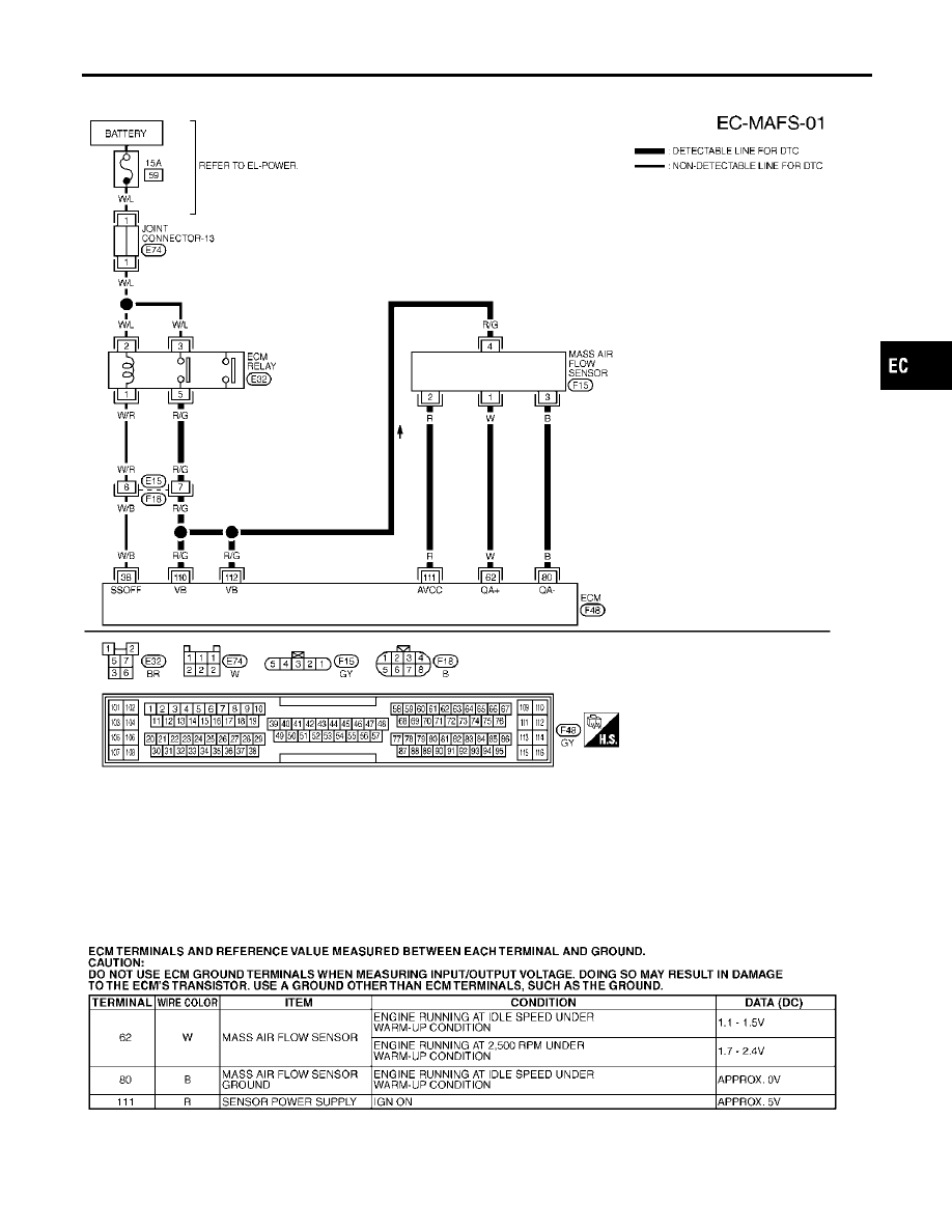
DTC P0102, P0103 MAF SENSOR
Wiring Diagram
EC-193
|
|
|
Wiring Diagram NHEC0753 MEC531D SEF650XE GI MA EM LC FE AT AX SU BR ST RS BT HA SC EL IDX DTC P0102, P0103 MAF SENSOR Wiring Diagram EC-193 |