Infiniti I30. Emission Control System (2003 year). Manual - part 9
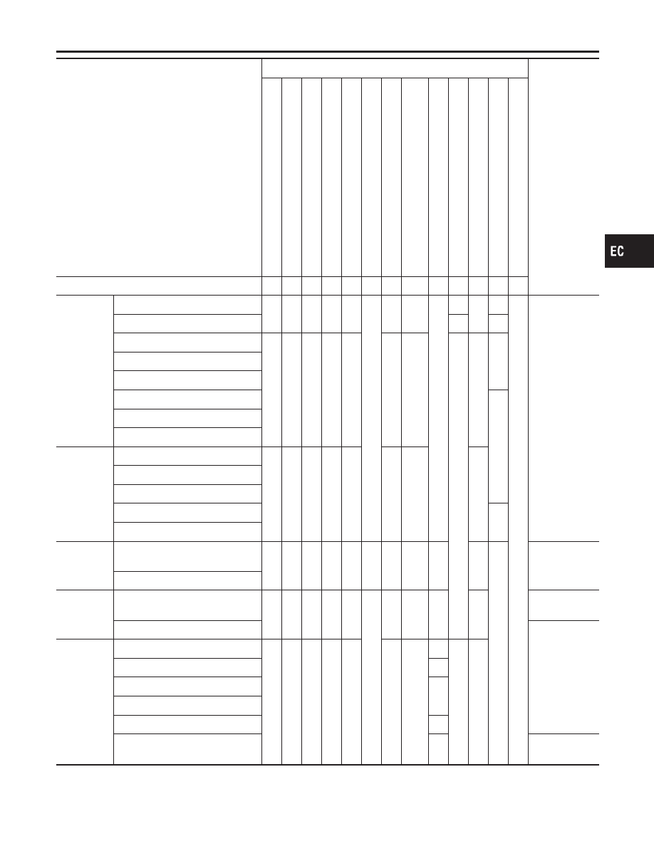
SYMPTOM
Reference
section
HARD/NO
ST
AR
T/REST
AR
T
(EXCP
.
HA)
ENGINE
ST
ALL
HESIT
A
TION/SURGING/FLA
T
SPOT
SP
ARK
KNOCK/DET
ONA
TION
LACK
OF
POWER/POOR
ACCELERA
TION
HIGH
IDLE/LOW
IDLE
ROUGH
IDLE/HUNTING
IDLING
VIBRA
TION
SLOW/NO
RETURN
T
O
IDLE
OVERHEA
TS/W
A
TER
TEMPERA
TURE
HIGH
EXCESSIVE
FUEL
CONSUMPTION
EXCESSIVE
OIL
CONSUMPTION
BA
TTER
Y
DEAD
(UNDER
CHARGE)
Warranty symptom code
AA AB AC AD AE AF AG
AH
AJ
AK AL AM HA
Engine
Cylinder head
5
5
5
5
5
5
5
5
EM section
Cylinder head gasket
4
3
Cylinder block
6
6
6
6
6
6
6
6
4
Piston
Piston ring
Connecting rod
Bearing
Crankshaft
Valve
mechanism
Timing chain
5
5
5
5
5
5
5
5
Camshaft
Intake valve timing control
Intake valve
3
Exhaust valve
Exhaust
Exhaust manifold/Tube/Muffler/
Gasket
5
5
5
5
5
5
5
5
FE section
Three way catalyst
Lubrication
Oil pan/Oil strainer/Oil pump/Oil
filter/Oil gallery
5
5
5
5
5
5
5
5
MA, EM, LC
section
Oil level (Low)/Filthy oil
LC section
Cooling
Radiator/Hose/Radiator filler cap
5
5
5
5
5
5
5
4
5
Thermostat
5
Water pump
Water gallery
Cooling fan
5
Coolant level (low)/Contaminated
coolant
MA section
1 - 6: The numbers refer to the order of inspection.
GI
MA
EM
LC
FE
AT
AX
SU
BR
ST
RS
BT
HA
SC
EL
IDX
TROUBLE DIAGNOSIS — GENERAL DESCRIPTION
Symptom Matrix Chart (Cont’d)
EC-129