Infiniti QX56 (JA60). Manual - part 951
TM-106
< ECU DIAGNOSIS >
TCM
ECU DIAGNOSIS
TCM
Reference Value
INFOID:0000000005148688
REFERENCE VALUES
NOTICE:
1. The CONSULT-III electrically displays shift timing and lock-up timing (that is, operation timing of each
solenoid).
Check for time difference between actual shift timing and the CONSULT-III display. If the difference is
noticeable, mechanical parts (except solenoids, sensors, etc.) may be malfunctioning. Check mechanical
parts using applicable diagnostic procedures.
2. Shift schedule (which implies gear position) displayed on CONSULT-III and that indicated in Service Man-
ual may differ slightly. This occurs because of the following reasons:
-
Actual shift schedule has more or less tolerance or allowance,
-
Shift schedule indicated in Service Manual refers to the point where shifts start, and
-
Gear position displayed on CONSULT-III indicates the point where shifts are completed.
3. Display of solenoid valves on CONSULT-III changes at the start of shifting, while gear position is displayed
upon completion of shifting (which is computed by TCM).
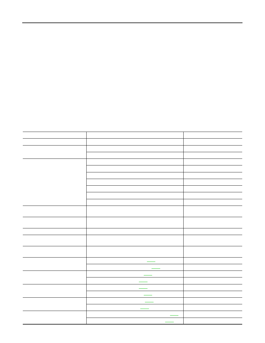
Item name
Condition
Display value (Approx.)
ATF TEMP SE 1
0
°C (32° F) - 20°C (68°F) - 80°C (176°F)
3.3 - 2.7 - 0.9 V
TCC SOLENOID
When perform slip lock-up.
0.2 - 0.4 A
When perform lock-up.
0.4 - 0.6 A
SLCT LVR POSI
Selector lever in “N”,“P” position.
N/P
Selector lever in “R” position.
R
Selector lever in “D” position.
D
Selector lever in “4” position.
4
Selector lever in “3” position.
3
Selector lever in “2” position.
2
Selector lever in “1” position.
1
VHCL/S SE-A/T
During driving
Approximately matches the
speedometer reading.
ENGINE SPEED
Engine running
Closely matches the tachometer
reading.
LINE PRES SOL
During driving
0.2 - 0.6 A
INPUT SPEED
During driving (lock-up ON)
Approximately matches the en-
gine speed.
VHCL/S SE-MTR
During driving
Approximately matches the
speedometer reading.
ATF PRES SW 2
Low coast brake engaged. Refer to
.
ON
Low coast brake disengaged. Refer to
OFF
I/C SOLENOID
Input clutch disengaged. Refer to
.
0.6 - 0.8 A
Input clutch engaged. Refer to
0 - 0.05 A
FR/B SOLENOID
0.6 - 0.8 A
Front brake disengaged. Refer to
.
0 - 0.05 A
D/C SOLENOID
Direct clutch disengaged. Refer to
.
0.6 - 0.8 A
Direct clutch engaged. Refer to
0 - 0.05 A
HLR/C SOL
High and low reverse clutch disengaged. Refer to
.
0.6 - 0.8 A
High and low reverse clutch engaged. Refer to
.
0 - 0.05 A