Infiniti QX56 (JA60). Manual - part 915


  Index      Infiniti     Infiniti QX56 (JA60) - service repair manual 2010 year


Search            


Content   ..  913  914  915  916   ..


Infiniti QX56 (JA60). Manual - part 915


TILT SYSTEM

ST-19

< REMOVAL AND INSTALLATION >

C

D

E

F

H

I

J

K

L

M

A

B

ST

N

O

P

TILT SYSTEM

Removal and Installation

INFOID:0000000005147871

TILT MOTOR AND TILT SENSOR

Removal

1. Remove the lower driver instrument panel. Refer to 

IP-11, "Exploded View"

.

2. Disconnect the sonar switch.
3. Disconnect adjustable pedal switch.
4. Remove steering column cover
5. Disconnect the tilt sensor electrical connector.
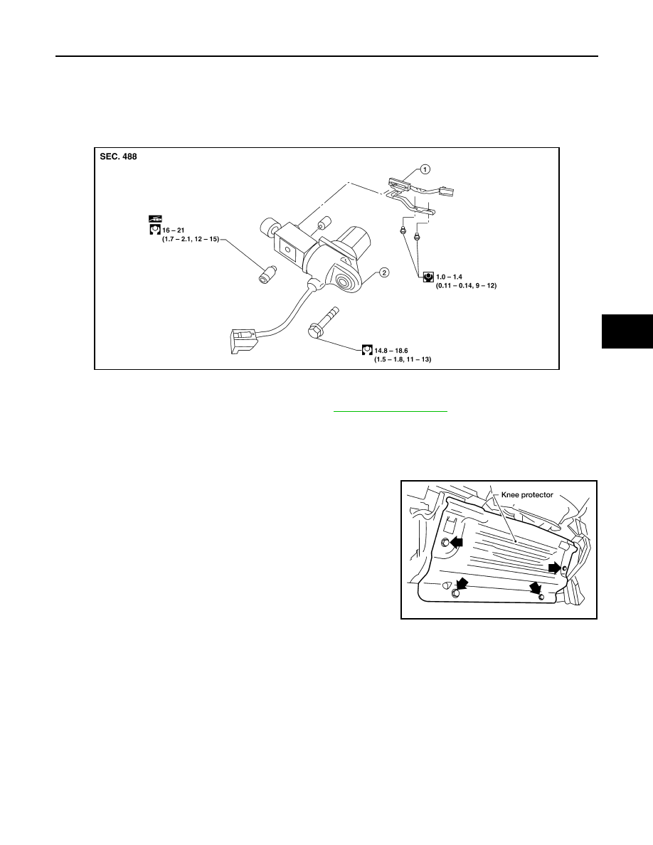
6. Remove knee protector.

7. Remove the two tilt sensor screws and the tilt sensor.
8. Disconnect the tilt motor electrical connector.
9. Remove the tilt motor bolt and the tilt motor.

Installation

Installation is in reverse order of removal.

NOTE:

Make sure the tab in the tilt sensor is engaged in the bracket on the tilt motor.

AWGIA0086GB

1.

Tilt sensor

2.

Tilt motor

LGIA0026E

ST-20

< REMOVAL AND INSTALLATION >

STEERING COLUMN

STEERING COLUMN

Removal and Installation

INFOID:0000000005147872

CAUTION:

• Any time the ignition switch has been disconnecter, removed or installed, the keys must be re-rege-

stered in the BCM. Refer toConsult-III operations IVIS/NVIS.

• Do not exert any load or impact in the axial direction immediately before or after column removal.

• Do not to move steering gear during removal of steering column assembly.

REMOVAL

1. Remove combination switch and spiral cable from steering column assembly. Refer to 

SR-7, "Removal

and Installation"

.

2. Remove the tilt motor and tilt sensor. Refer to 

ST-19, "Removal and Installation"

.

3. Remove steering column cover. Refer to 

ST-20, "Removal and Installation"

.

1.

Driver air bag module

2.

Steering wheel

3.

Steering wheel side cover

4.

Combination switch and spiral cable 5.

Steering column assembly

6.

Collar

7.

Hole cover seal

8.

Clamp

9.

Hole cover plate

10. Hole cover

11. Upper joint

12. Upper shaft

13. Boot clamp

14. Lower joint shaft

15. Boot and clips (plastic)

A.

Refer to 

SR-5, "Removal and Installation"

AWGIA0113GB

STEERING COLUMN

ST-21

< REMOVAL AND INSTALLATION >

C

D

E

F

H

I

J

K

L

M

A

B

ST

N

O

P

4. Remove lock nut and bolt, then separate upper shaft from upper

joint.

5. Remove two nuts and two bolts, then remove steering column

assembly from steering member.

6. Remove hole cover seal and clamp.
7. Remove nuts, then remove hole cover from dash panel.
8. Raise vehicle, then remove bolt (lower side) of lower joint shaft

and remove lower joint shaft and upper shaft as an assembly.

INSPECTION AFTER REMOVAL

• Check for damage to steering column jacket tube. If damage is found, replace steering column with new

one.

• If vehicle has been in a collision, check column length (L), (L

1

) and (L

2

) as shown. If out of specification,

replace steering column with new one.

LGIA0027E

LGIA0028E

LGIA0029E

Steering column length
(L)

: Refer to 

ST-35, "Steering Column"

(L

1

)

: Refer to 

ST-35, "Steering Column"

(L

2

)

: Refer to 

ST-35, "Steering Column"

WGIA0080E

ST-22

< REMOVAL AND INSTALLATION >

STEERING COLUMN

• Check for proper lubrication, apply grease as necessary.

INSTALLATION

Installation is in the reverse order of removal.

CAUTION:

• When installing the steering column, finger-tighten all of the lower bracket and joint retaining bolts;

then tighten them to specification. Do not apply undue stress to the steering column.

• The lower nut on the upper joint may not be reused.

NOTE:

• After installation, turn steering wheel to make sure it moves smoothly. Make sure the number of turns are the

same from the straight-forward position to left and right locks. Make sure that the steering wheel is in a neu-

tral position when driving straight ahead.

• When installing steering column to steering member, install nut from front side of vehicle.

INSPECTION AFTER INSTALLATION

• After installing steering column to vehicle, check tilt device operation range is within specification.

• Check if steering wheel operation can turn to the end of the left and

right stops smoothly.

SGIA0475E

Range "A"

: Refer to 

ST-35, "Steering Column"

WGIA0083E


Content   ..  913  914  915  916   ..