Infiniti QX56 (JA60). Manual - part 813


  Index      Infiniti     Infiniti QX56 (JA60) - service repair manual 2010 year


Search            


Content   ..  811  812  813  814   ..


Infiniti QX56 (JA60). Manual - part 813


POWER SUPPLY AND GROUND CIRCUIT

SCS-17

< COMPONENT DIAGNOSIS >

C

D

F

G

H

I

J

K

L

M

A

B

SCS

N

O

P

POWER SUPPLY AND GROUND CIRCUIT

SUSPENSION CONTROL UNIT
SUSPENSION CONTROL UNIT : Diagnosis Procedure

INFOID:0000000005148175

Regarding Wiring Diagram information, refer to 

SCS-29, "Wiring Diagram"

.

1.

CHECK FUSES

Check that the following fuses of the suspension control unit are not are not blown.

Are the fuses OK?

YES

>> GO TO 2.

NO

>> If fuse is blown, be sure to eliminate cause of malfunction before installing new fuse.

2.

POWER SUPPLY CIRCUIT CHECK

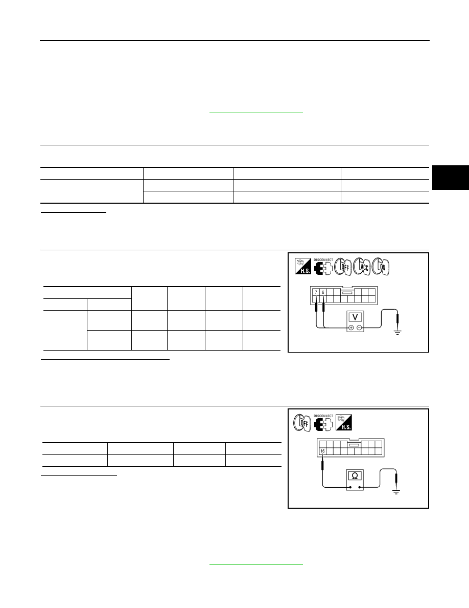
1. Disconnect suspension control unit connector B3. 

2. Check voltage between the suspension control unit connector

B3 and ground.

Are the voltage results as specified?

YES

>> GO TO 3.

NO

>> • Check connector housings for disconnected or loose terminals.

• Repair harness or connector.

3.

GROUND CIRCUIT CHECK

1. Turn ignition switch OFF.

2. Check continuity between suspension control unit harness con-

nector B3 and ground.

Is continuity present?

YES

>> Inspection End.

NO

>> Repair harness or connector.

SUSPENSION AIR COMPRESSOR
SUSPENSION AIR COMPRESSOR : Diagnosis Procedure

INFOID:0000000005148176

Regarding Wiring Diagram information, refer to 

SCS-29, "Wiring Diagram"

.

Unit

Terminals

Signal name

Fuse No.

Suspension control unit

7

Battery power

29

6

Ignition switch ON or START

12

(+)

(-)

OFF

ACC

ON

Connector

Terminal

B3

7

Ground

Battery 
voltage

Battery 
voltage

Battery 
voltage

6

Ground

0V

0V

Battery 
voltage

AWEIA0114ZZ

Connector

Terminal

Continuity

B3

16

Ground

Yes

ALEIA0028GB

SCS-18

< COMPONENT DIAGNOSIS >

POWER SUPPLY AND GROUND CIRCUIT

1.

CHECK COMPRESSOR MOTOR RELAY OPRATION

CONSULT-III

1. Disconnect the suspension air compressor connector C9.

2. Turn ignition switch ON.

3. Select "COMPRESSOR" under AIR LEVELIZER active test

items.

4. While operating the test item, check voltage at the suspension

air compressor connector C9 terminal 4.

Is battery voltage present?

YES

>> GO TO 3.

NO

>> GO TO 2.

2.

COMPRESSOR MOTOR RELAY POWER SUPPLY CIRCUIT CHECK

1. Turn ignition switch OFF.

2. Disconnect the compressor motor relay connector.

3. Check continuity between compressor motor relay connector

E131 (A) terminal 3 and suspension air compressor connector

C9 (B) terminal 4.

4. Check continuity between compressor motor relay connector

E131 (A) terminal 3 and ground.

Are the continuity test results as specified?

YES

>> Check compressor motor relay.  Refer to 

SCS-20, "Diagnosis Procedure"

.

NO

>> Repair harness or connector.

3.

GROUND CIRCUIT CHECK

1. Turn ignition switch OFF.

2. Check continuity between suspension air compressor connector

C9 terminals 1 and 3 and ground.

Is continuity present?

YES

>> Inspection End.

NO

>> Repair harness or connector.

HEIGHT SENSOR
HEIGHT SENSOR : Diagnosis Procedure

INFOID:0000000005148177

Regarding Wiring Diagram information, refer to 

SCS-29, "Wiring Diagram"

.

(+)

(-)

Voltage

Connector

Terminal

C9

4

Ground

Battery Voltage

ALEIA0021GB

A

B

Continuity

Connector

Terminal

Connector

Terminal

E131

3

C9

4

Yes

A

Continuity

Connector

Terminal

E131

3

Ground

No

ALEIA0022GB

Connector

Terminal

Continuity

C9

1

Ground

Yes

3

ALEIA0023GB

POWER SUPPLY AND GROUND CIRCUIT

SCS-19

< COMPONENT DIAGNOSIS >

C

D

F

G

H

I

J

K

L

M

A

B

SCS

N

O

P

1.

POWER SUPPLY CIRCUIT CHECK

1. Disconnect height sensor connector C8.

2. Turn the ignition switch ON. 

3. Check voltage between the height sensor connector C8 terminal

1 and ground.

Is 5V present?

YES

>> GO TO 2.

NO

>> Check harness or connector for open or short. If OK,

replace the suspension control unit. Refer to 

RSU-26, "Removal and Installation"

.

2.

GROUND CIRCUIT CHECK

1. Turn ignition switch OFF.

2. Check continuity between height sensor connector C8 terminal

3 and ground.

Is continuity present?

YES

>> Ground circuit is OK.

NO

>> Repair harness or connector.

(+)

(-)

Voltage

Connector

Terminal

C8

1

Ground

5V

ALEIA0026GB

Connector Terminal

Continuity

C8

3

Ground

Yes

ALEIA0029GB

SCS-20

< COMPONENT DIAGNOSIS >

COMPRESSOR MOTOR RELAY

COMPRESSOR MOTOR RELAY

Description

INFOID:0000000005148178

Receives suspension air compressor ON signal from suspension control unit. When activated, the compressor

motor relay supplies power to the suspension air compressor. 

Component Function Check

INFOID:0000000005148179

1.

CHECK COMPRESSOR MOTOR RELAY OPERATION

CAUTION:

The "COMPRESSOR" active test will remain ON until it is turned off using CONSULT-III. Allowing the

compressor to run for an extended period of time may cause damage to the suspension control sys-

tem components due to excessive air pressure.

CONSULT-III

1. Turn ignition ON.

2. Select "COMPRESSOR" of AIR LEVELIZER active test items.

3. While operating test item, check that the suspension air compressor turns ON.

Does the suspension air compressor operate properly?

YES

>> Compressor motor relay and suspension air compressor are operating normally.

NO

>> Refer to 

SCS-20, "Diagnosis Procedure"

.

Diagnosis Procedure

INFOID:0000000005148180

Regarding Wiring Diagram information, refer to 

SCS-29, "Wiring Diagram"

.

1.

CHECK COMPRESSOR "ON" SIGNAL FROM SUSPENSION CONTROL UNIT

CONSULT-III

1. Turn ignition switch ON.

2. Disconnect compressor motor relay connector E130.

3. Select "COMPRESSOR" of AIR LEVELIZER active test items.

4. While operating test item, check voltage to compressor motor

relay connector E130 terminal 2.

Is battery voltage present while operating test item?

YES

>> GO TO 3.

NO

>> GO TO 2.

2.

CHECK COMPRESSOR "ON" SIGNAL CIRCUIT

ON

: Compressor turns ON

OFF

: Compressor turns OFF

(+)

(-)

Voltage

Connector

Terminal

E130

2

Ground

Battery voltage

ALEIA0030GB


Content   ..  811  812  813  814   ..