Infiniti QX56 (JA60). Manual - part 711
MWI
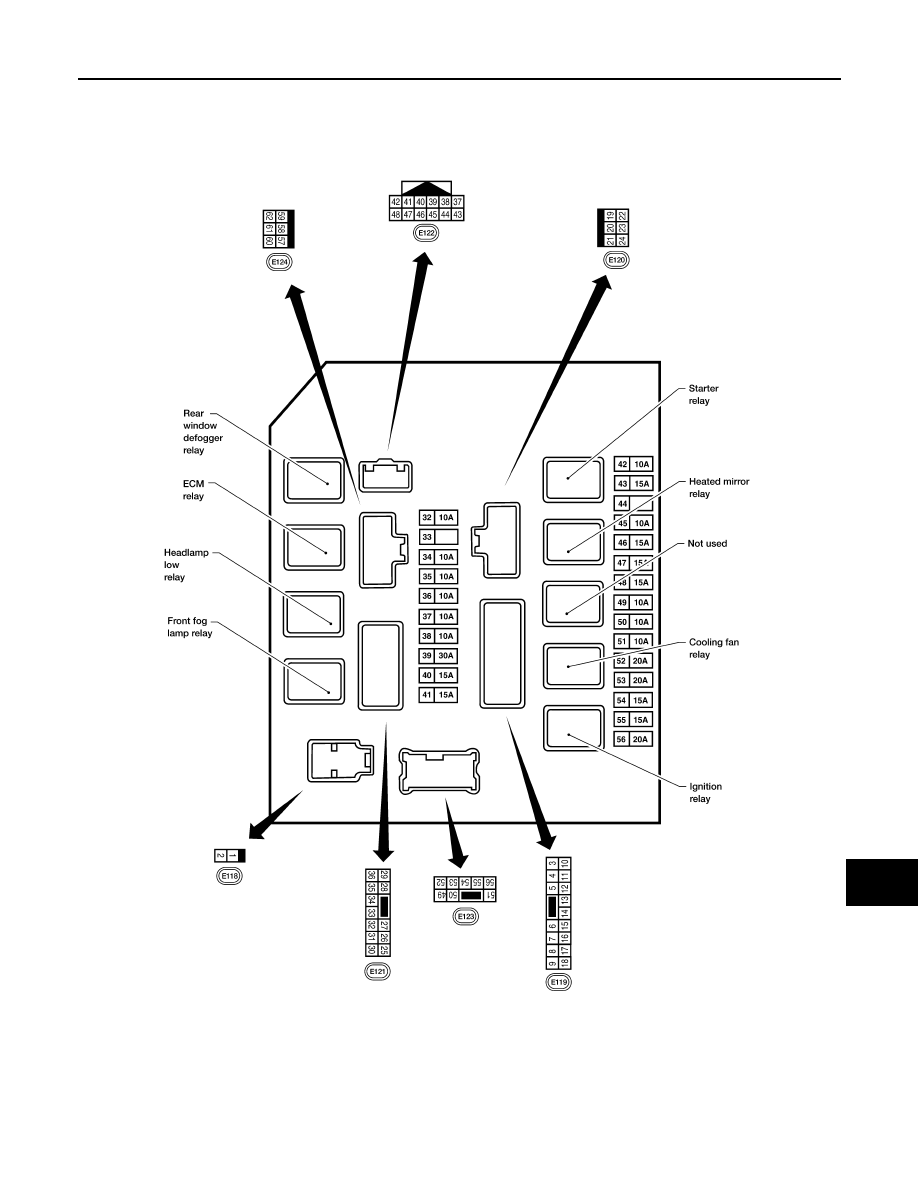
IPDM E/R (INTELLIGENT POWER DISTRIBUTION MODULE ENGINE ROOM)
MWI-79
< ECU DIAGNOSIS >
C
D
E
F
G
H
I
J
K
L
M
B
A
O
P
Terminal Layout
INFOID:0000000005380665
TERMINAL LAYOUT —TYPE A
WKIA5852E
|
|
|
MWI IPDM E/R (INTELLIGENT POWER DISTRIBUTION MODULE ENGINE ROOM) MWI-79 < ECU DIAGNOSIS > C D E F G H I J K L M B A O P Terminal Layout INFOID:0000000005380665 TERMINAL LAYOUT —TYPE A WKIA5852E |