Infiniti QX56 (JA60). Manual - part 675


  Index      Infiniti     Infiniti QX56 (JA60) - service repair manual 2010 year


Search            


Content   ..  673  674  675  676   ..


Infiniti QX56 (JA60). Manual - part 675


OIL FILTER

LU-11

< ON-VEHICLE MAINTENANCE >

C

D

E

F

G

H

I

J

K

L

M

A

LU

N

P

O

OIL FILTER

Removal and Installation

INFOID:0000000005149027

REMOVAL

1. Drain the engine oil. Refer to 

LU-9, "Changing Engine Oil"

.

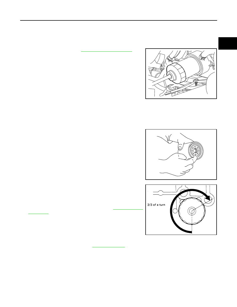
2. Remove the oil filter using Tool.

WARNING:

• Be careful not to get burned when the engine and engine

oil are hot.

CAUTION:

• The oil filter is provided with a relief valve.

• Use Genuine NISSAN oil filter or equivalent.

• When removing, prepare a shop cloth to absorb any

engine oil leakage or spillage.

• Do not allow engine oil to adhere to the drive belts.

• Completely wipe off any engine oil that adheres to the engine and the vehicle.

INSTALLATION

1. Remove foreign materials adhering to the oil filter installation surface.
2. Apply engine oil to the oil seal circumference of the new oil filter.

3. Screw the oil filter manually until it touches the installation sur-

face, then tighten it by 2/3 turn. Or tighten to specification.

4. Refill the engine with new engine oil. Refer to 

LU-9, "Changing

Engine Oil"

.

5. Inspect the engine for oil leakage. Follow the "INSPECTION

AFTER INSTALLATION" procedure.

INSPECTION AFTER INSTALLATION

1. Check the engine oil level. Refer to 

LU-8, "Inspection"

.

2. Start the engine and check for engine oil leakage.
3. Stop the engine and wait for 10 minutes.
4. Check the engine oil level and add engine oil as required.

Tool number

: KV10115801 (J-38956)

WBIA0388E

SMA010

Oil filter

: 17.7 N·m (1.8 kg-m, 13 ft-lb)

SMA229B

LU-12

< ON-VEHICLE REPAIR >

OIL COOLER

ON-VEHICLE REPAIR

OIL COOLER

Exploded View

INFOID:0000000005149028

Removal and Installation

INFOID:0000000005149029

WARNING:

Be careful not to burn yourself, as the engine oil and engine coolant are hot.

REMOVAL

1. Drain engine coolant from the radiator. Refer to 

CO-11, "Changing Engine Coolant"

.

2. Disconnect water hoses from the oil cooler.

CAUTION:

Do not spill engine coolant on the drive belt.

3. Remove oil filter. Refer to 

LU-11, "Removal and Installation"

.

CAUTION:

Do not spill engine oil on the drive belt.

4. Remove connector bolt, and remove oil cooler.

INSPECTION AFTER REMOVAL

Oil Cooler

Check oil cooler for cracks. Check oil cooler for clogging by blowing compressed air through engine coolant

inlet. If necessary, replace oil cooler assembly. 

1.

Oil pan

2.

Water hose

3.

Water pipe

4.

Water hose

5.

Connector bolt

6.

Oil filter

7.

Oil cooler

8.

O-ring

9.

Relief valve

10. Water hose

11. Connector pipe

12. Gasket

A.

To thermostat housing

B.

Refer to 

LU-11

C.

To cylinder block

WBIA0790E

OIL COOLER

LU-13

< ON-VEHICLE REPAIR >

C

D

E

F

G

H

I

J

K

L

M

A

LU

N

P

O

Relief Valve

Inspect relief valve for movement, cracks and breaks by pushing the ball. If replacement is necessary, remove

the valve by prying it out using a suitable tool. Install a new valve in place by tapping it.

INSTALLATION

Installation is in the reverse order of removal, paying attention to the following:

• Confirm that no foreign objects are adhering to the sealing sur-

faces of the oil cooler or oil pan. 

• Tighten the connecting bolt after aligning the stopper on the oil pan

side with protrusion of the oil cooler.

INSPECTION AFTER INSTALLATION

1. Check levels and add engine oil and engine coolant. Refer to 

LU-8, "Inspection"

 and 

CO-10, "Inspection"

.

2. Start the engine, and check for leaks of engine oil and engine coolant.
3. Stop the engine and wait for 10 minutes.
4. Check engine oil level and engine coolant level again.

KBIA2500E

LU-14

< ON-VEHICLE REPAIR >

OIL PUMP

OIL PUMP

Exploded View

INFOID:0000000005149030

Removal and Installation

INFOID:0000000005149031

REMOVAL

1. Remove front cover. Refer to 

EM-44, "Exploded View"

2. Remove the oil pump drive spacer.
3. Remove the oil pump.

INSTALLATION

Installation is in the reverse order of removal, paying attention of the following:

• When inserting the oil pump drive spacer, align the crankshaft key

and the flat face of the inner rotor.

• If they are not aligned, rotate the oil pump inner rotor by hand.

• Make sure that each part is aligned and tap lightly until it reaches

the end.

INSPECTION AFTER INSTALLATION

1.

Oil pump body

2.

Outer rotor

3.

Inner rotor

4.

Oil pump cover

5.

Oil pump drive spacer

6.

Regulator valve

7.

Regulator spring

8.

Regulator plug

WBIA0415E

KBIA2512E

KBIA2490E


Content   ..  673  674  675  676   ..