Infiniti QX56 (JA60). Manual - part 593


  Index      Infiniti     Infiniti QX56 (JA60) - service repair manual 2010 year


Search            


Content   ..  591  592  593  594   ..


Infiniti QX56 (JA60). Manual - part 593


MODE DOOR MOTOR

HAC-29

< COMPONENT DIAGNOSIS >

[AUTOMATIC AIR CONDITIONER]

C

D

E

F

G

H

J

K

L

M

A

B

HAC

N

O

P

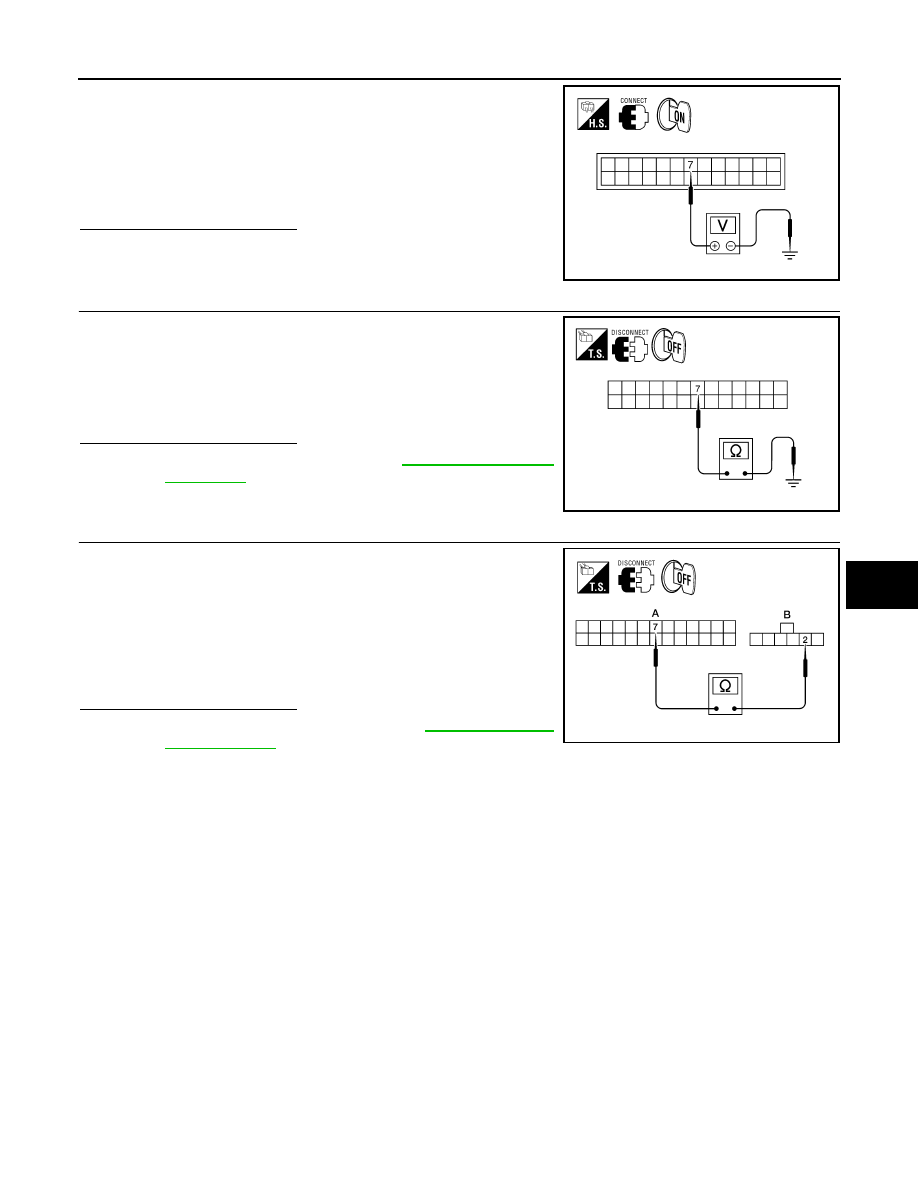
1. Reconnect the A/C auto amp. harness connector.

2. Turn ignition switch ON.

3. Check voltage between A/C auto amp. harness connector M49

terminal 7 and ground while cycling mode switch through all

modes.

Is the inspection result normal?

YES

>> GO TO 12.

NO

>> GO TO 11.

11.

CHECK PBR FEEDBACK SIGNAL CIRCUIT FOR SHORT TO GROUND

1. Turn ignition switch OFF.

2. Disconnect A/C auto amp. harness connector.

3. Check continuity between A/C auto amp. harness connector

M49 terminal 7 and ground.

Is the inspection result normal?

YES

>> Replace A/C auto amp. Refer to 

VTL-7, "Removal and

Installation"

.

NO

>> Repair or replace harness as necessary.

12.

CHECK PBR FEEDBACK CIRCUIT FOR OPEN

1. Turn ignition switch OFF.

2. Disconnect the mode door motor harness connector and A/C

auto amp. harness connector.

3. Check continuity between mode door motor harness connector

M142 (B) terminal 2 and A/C auto amp. harness connector M49

(A) terminal 7.

Is the inspection result normal?

YES

>> Replace mode door motor. Refer to 

VTL-29, "Removal

and Installation"

.

NO

>> Repair or replace harness as necessary.

 Voltage

: Approx. 1V - 4.5V

AWIIA0103ZZ

Continuity should not exist.

AWIIA0104ZZ

Continuity should exist.

AWIIA0105ZZ

HAC-30

< COMPONENT DIAGNOSIS >

[AUTOMATIC AIR CONDITIONER]

AIR MIX DOOR MOTOR

AIR MIX DOOR MOTOR

System Description

INFOID:0000000005147690

SYSTEM DESCRIPTION

SYMPTOM:

• Discharge air temperature does not change.

• Air mix door motor does not operate.

SYSTEM DESCRIPTION

Component Parts

Air mix door control system components are:

• A/C auto amp.

• A/C and AV switch assembly

• Air mix door motors (driver, passenger, and rear)

• PBR (built-into air mix door motors)

• In-vehicle sensor

• Ambient sensor

• Optical sensor

• Intake sensor

System Operation

The A/C auto amp. receives data from the temperature selected by the driver side, passenger side, and rear.

The A/C auto amp. then applies a voltage to one circuit of the appropriate air mix door motor, while ground is

applied to the other circuit, causing the appropriate air mix door motor to rotate. The direction of rotation is

determined by which circuit has voltage applied to it, and which one has ground applied to it. The A/C auto

amp. monitors the air mix door positions by measuring the voltage signal on the PBR circuits of each door.

In AUTO mode the air mix, intake, mode door, and defrost door positions are set by the A/C auto amp. which

determines the proper position based on inputs from the in-vehicle sensor, ambient sensor, optical sensor,

intake sensor, and the temperature selected by the driver and front and rear passengers.

Subsequently, HOT/COLD or DEFROST/VENT or FRESH/RECIRCULATION operation is selected. The new

door position data is returned to the A/C auto amp.

AWIIA0106GB

AIR MIX DOOR MOTOR

HAC-31

< COMPONENT DIAGNOSIS >

[AUTOMATIC AIR CONDITIONER]

C

D

E

F

G

H

J

K

L

M

A

B

HAC

N

O

P

Air Mix Door Control Specification

COMPONENT DESCRIPTION

Air Mix Door Motors (front)

The driver (1) and passenger (2) air mix door motors are attached to

the front heater & cooling unit assembly. These motors rotate so that

the air mix door is opened or closed to a position set by the A/C auto

amp. Motor rotation is then conveyed through a shaft and the air mix

door position is then fed back to the A/C auto amp. by the PBR built

into the air mix door motors.

Air Mix Door Motor (rear)

The air mix door motor (rear) (1) is attached to the rear heater &

cooling unit assembly. These motors rotate so that the air mix door is

opened or closed to a position set by the front (or rear) air control.

Motor rotation is then conveyed through a shaft and the air mix door

position is then fed back to the A/C auto amp. by the PBR built into

the air mix door motors.

Air Mix Door Motor (Driver) Component Function Check

INFOID:0000000005147691

INSPECTION FLOW

1.

CONFIRM SYMPTOM BY PERFORMING OPERATIONAL CHECK - TEMPERATURE INCREASE

1. Turn the temperature control dial (driver) clockwise until 32

°C (90°F) is displayed.

2. Check for hot air at discharge air outlets.

>> GO TO 2.

2.

CONFIRM SYMPTOM BY PERFORMING OPERATIONAL CHECK - TEMPERATURE DECREASE

1. Turn the temperature control dial (driver) counterclockwise until 18

°C (60°F) is displayed.

2. Check for cold air at discharge air outlets.
Is the inspection result normal?

YES

>> Inspection End.

NO

>> Go to diagnosis procedure. Refer to 

HAC-32, "Air Mix Door Motor (Driver) Diagnosis Procedure"

.

AWIIA0107GB

AWIIA0109ZZ

AWIIA0111ZZ

HAC-32

< COMPONENT DIAGNOSIS >

[AUTOMATIC AIR CONDITIONER]

AIR MIX DOOR MOTOR

Air Mix Door Motor (Driver) Diagnosis Procedure

INFOID:0000000005147692

Regarding Wiring Diagram information, refer to 

HAC-91, "Wiring Diagram"

.

SYMPTOM:

• Discharge air temperature does not change.

• Air mix door motor does not operate.

DIAGNOSTIC PROCEDURE FOR AIR MIX DOOR MOTOR (DRIVER)

1.

CHECK A/C AUTO AMP. FOR POWER AND GROUND 

1. Turn ignition switch ON.

2. Rotate temperature control dial (driver) to 32

°C (90°F).

3. Check voltage between A/C auto amp. harness connector M49

terminal 17 and terminal 18 while rotating temperature control

dial (driver) to 18

°C (60°F).

Is the inspection result normal?

YES

>> GO TO 3.

NO

>> GO TO 2.

2.

CHECK AIR MIX DOOR MOTOR (DRIVER) CIRCUITS FOR SHORT TO GROUND 

1. Turn ignition switch OFF.

2. Disconnect the A/C auto amp. harness connector.

3. Check continuity between A/C auto amp. harness connector

M49 terminal 17, 18 and ground.

Is the inspection result normal?

YES

>> Replace A/C auto amp. Refer to 

VTL-7, "Removal and

Installation"

.

NO

>> Repair or replace harness as necessary.

3.

CHECK A/C AUTO AMP. FOR POWER AND GROUND 

1. Turn ignition switch ON.

2. Rotate temperature control dial (driver) to 32

°C (90°F).

3. Check voltage between A/C auto amp. harness connector M49

terminal 17 and terminal 18 while rotating temperature control

dial (driver) to 18

°C (60°F).

Is the inspection result normal?

YES

>> GO TO 4.

NO

>> Replace A/C auto amp. Refer to 

VTL-7, "Removal and Installation"

.

Connector

Terminals

Condition 

Voltage 

(Approx.)

(+) (-)

A/C auto amp.: 

M49

17 18

Rotate temp 

control dial

Battery 
voltage

AWIIA0112ZZ

17 - Ground

: Continuity should not exist.

18 - Ground

: Continuity should not exist.

AWIIA0114ZZ

Connector

Terminals

Condition 

Voltage 

(Approx.)

(+) (-)

A/C auto amp.: 

M49

18 17

Rotate temp 

control dial

Battery 
voltage

AWIIA0115ZZ


Content   ..  591  592  593  594   ..