Infiniti QX56 (JA60). Manual - part 505
HEADLAMP AIMING SWITCH
EXL-49
< COMPONENT DIAGNOSIS >
C
D
E
F
G
H
I
J
K
M
A
B
EXL
N
O
P
HEADLAMP AIMING SWITCH
Description
INFOID:0000000005146660
The manual headlamp aiming system uses a headlamp aiming switch to adjust the axis of the headlamp aim-
ing motor. The headlamp aiming switch has four settings, each with a different resistance value. The head-
lamp aiming motor adjusts to the proper axis based off the position of the headlamp aiming switch.
Diagnosis Procedure - Without Daytime Light System
INFOID:0000000005146661
Regarding Wiring Diagram information, refer to
.
1.
CHECK HEADLAMP AIMING SWITCH SIGNAL FOR OPEN OR SHORT CIRCUIT
1. Turn ignition switch OFF.
2. Disconnect headlamp aiming switch connector M148 (A), headlamp aiming motor LH connector E11 and
headlamp aiming motor RH connector E107 (B).
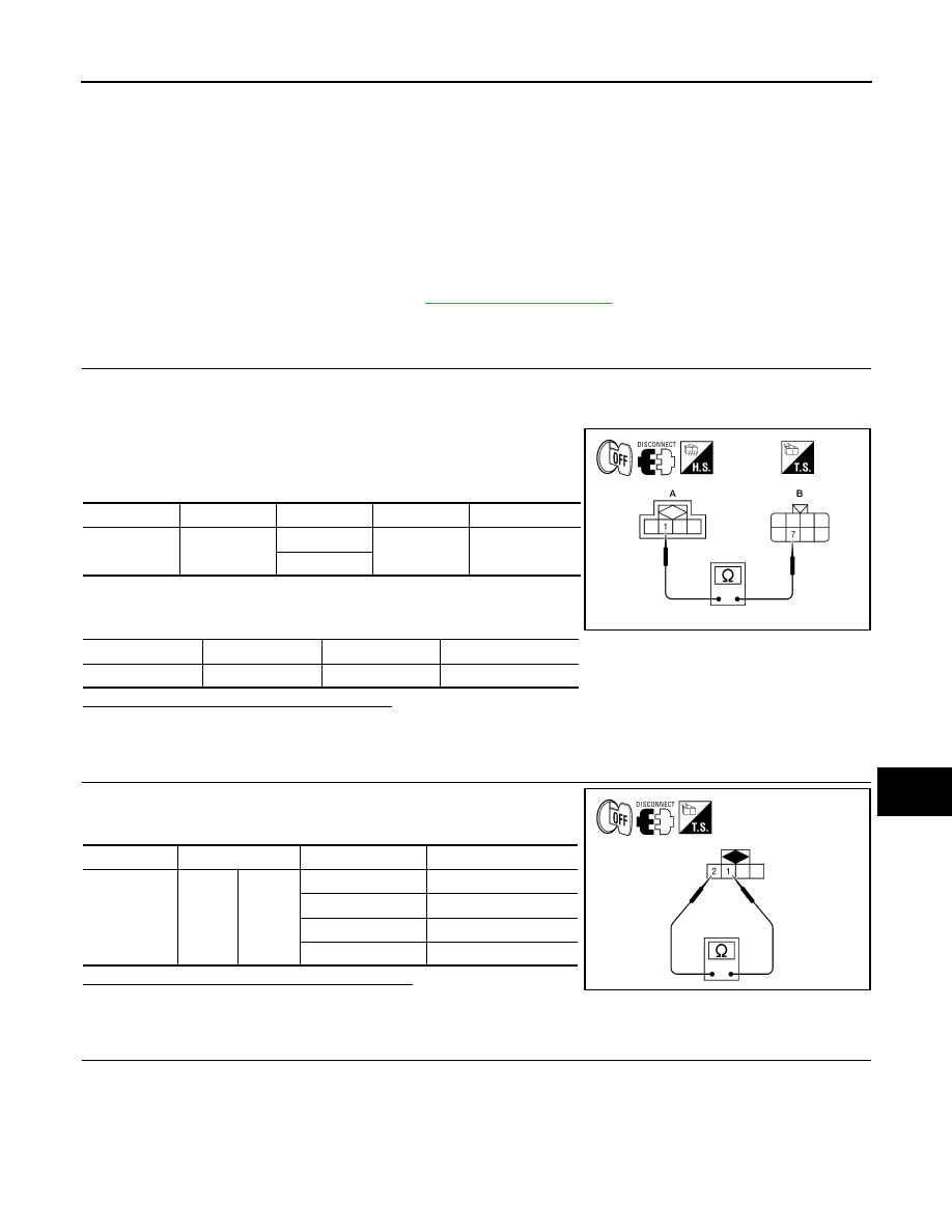
3. Check continuity between the headlamp aiming switch connec-
tor M148 terminal 1 (A) and headlamp aiming motor LH E11 and
RH E107 terminal 7 (B).
4. Check continuity between the headlamp aiming switch connec-
tor M148 terminal 1 and ground.
Are the continuity test results as specified?
YES
>> GO TO 2.
NO
>> Repair the harness or connector.
2.
CHECK HEADLAMP AIMING SWITCH
1. Check resistance between the headlamp aiming switch termi-
nals 1 and 2 in each switch position.
Are the resistance check results as specified?
YES
>> GO TO 3.
NO
>> Replace the headlamp aiming switch.
3.
CHECK HEADLAMP AIMING SWITCH GROUND CIRCUIT
Connector
Terminal
Connector
Terminal
Continuity
M148
1
E11
7
Yes
E107
Connector
Terminal
—
Continuity
M148
1
Ground
No
AWLIA1093ZZ
Component
Terminal
Switch Position
Resistance
Headlamp
aiming switch
1
2
0
604
Ω
1
324
Ω
2
191
Ω
3
130
Ω
AWLIA1027ZZ