Infiniti QX56 (JA60). Manual - part 474


  Index      Infiniti     Infiniti QX56 (JA60) - service repair manual 2010 year


Search            


Content   ..  472  473  474  475   ..


Infiniti QX56 (JA60). Manual - part 474


EM-50

< ON-VEHICLE REPAIR >

TIMING CHAIN

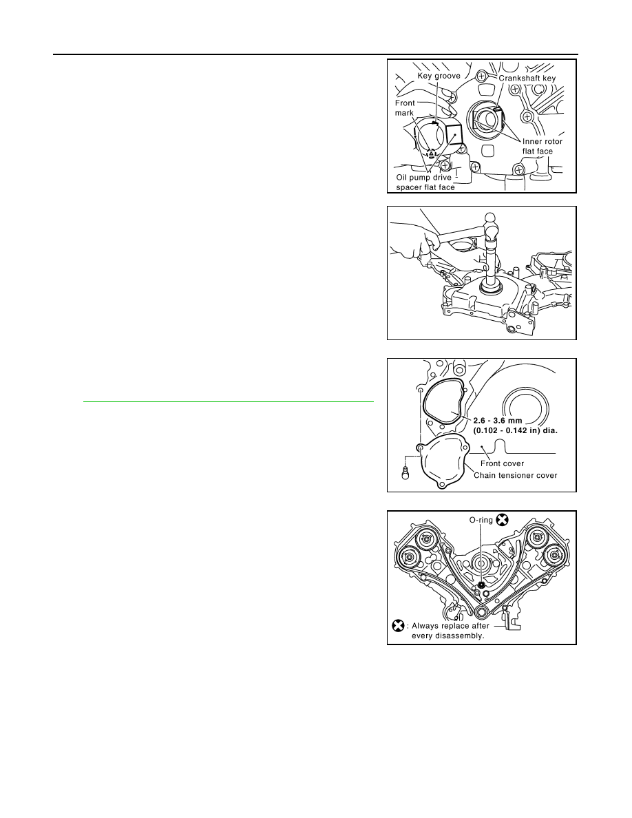
7. Install the oil pump drive spacer as follows:

• Install so that the front mark on the front edge of the oil pump

drive spacer faces the front of the engine.

• Insert the oil pump drive spacer according to the directions of

the crankshaft key and the two flat surfaces of the oil pump

inner rotor. 

• If the positional relationship does not allow the insertion, rotate

the oil pump inner rotor to allow the oil pump drive spacer to

be inserted.

8. Install the front oil seal using suitable tool.

CAUTION:

Do not scratch or make burrs on the circumference of the

oil seal.

9. Install the chain tensioner cover.

• Apply liquid gasket as shown.

Use Genuine RTV Silicone Sealant or equivalent. Refer to

GI-15, "Recommended Chemical Products and Sealants"

10. Install the front cover as follows:
a. Install a new O-ring on the cylinder block.

KBIA2490E

PBIC0059E

KBIA2547E

KBIA2516E

TIMING CHAIN

EM-51

< ON-VEHICLE REPAIR >

C

D

E

F

G

H

I

J

K

L

M

A

EM

N

P

O

b. Apply liquid gasket as shown.

Use Genuine RTV Silicone Sealant or equivalent. Refer to

GI-15, "Recommended Chemical Products and Sealants"

.

c. Check again that the timing alignment marks on the timing chain

and on each sprocket are aligned. Then install the front cover.

d. Install the bolts in the numerical order shown.

e. After tightening, re-tighten to the specified torque.

CAUTION:

Be sure to wipe off any excessive liquid gasket leaking onto

surface mating with oil pan.

11. Install the Intake valve timing control solenoid valve cover (RH)

(A) and Intake valve timing control solenoid valve cover (LH) (B)

as follows:

• Cross mark that can not be seen after assembly (C)

a. Apply liquid gasket (D) as shown.

Use Genuine RTV Silicone Sealant or equivalent. Refer to

GI-15, "Recommended Chemical Products and Sealants"

.

CAUTION:

The start and end of the application of the liquid gasket

should be crossed at a position (C) that cannot be seen

after attaching the chain case cover.

b. Install the bolts and tighten them to specification in the numeri-

cal order shown.

• A: Intake valve timing control solenoid valve cover (RH) 

• B: Intake valve timing control solenoid valve cover (LH)

12. Install the crankshaft pulley.

• Install the key of the crankshaft.

• Insert the pulley by lightly tapping it.

CAUTION:

Do not tap pulley on the side surface where the belt is installed (outer circumference).

13. Tighten the crankshaft pulley bolt.

• Lock the crankshaft using suitable tool, then tighten the bolt. 

• Perform the following steps for angular tightening:

a. Apply engine oil onto the threaded parts of the bolt and seating area.

KBIA2517E

M6 

× 50 mm (1.97 in)

: No. 1, 20, 25, 26, 27

M6 

× 80 mm (3.15 in)

: No. 4, 5, 7

M6 

× 20 mm (0.79 in)

: Except the above

KBIA2478E

D : 2.6 - 3.6 mm (0.102 - 0.142 in) dia.

WBIA0800E

AWBIA0815ZZ

EM-52

< ON-VEHICLE REPAIR >

TIMING CHAIN

b. Select the one most visible notch of the four on the bolt flange.

Corresponding to the selected notch, put a alignment mark

(such as paint) on the crankshaft pulley. 

14. Rotate the crankshaft pulley in normal direction (clockwise when

viewed from engine front) to check for parts interference.

15. Installation of the remaining components is in the reverse of

order of removal.

INSPECTION AFTER INSTALLATION

• Before starting the engine, check oil/fluid levels including engine coolant and engine oil. If the levels are

lower than required quantity, fill to the specified level. Refer to 

MA-13, "Fluids and Lubricants"

.

• Use procedure below to check for fuel leakage.

• Turn ignition switch ON (with engine stopped). With fuel pressure applied to the fuel piping, check for fuel

leakage at the connection points.

• Start engine. With engine speed increased, check again for fuel leakage at connection points.

• Run engine to check for unusual noise and vibration.

NOTE:

If hydraulic pressure inside timing chain tensioner drops after removal and installation, slack in the guide

may generate a pounding noise during and just after engine start. However, this is normal. Noise will stop

after hydraulic pressure rises.

• Warm up engine thoroughly to make sure there is no leakage of fuel, exhaust gas, or any oils/fluids including

engine oil and engine coolant.

• Bleed air from passages in lines and hoses, such as in cooling system.

• After cooling down the engine, again check oil/fluid levels including engine oil and engine coolant. Refill to

specified level if necessary.

• Summary of the inspection items:

*Transmission/transaxle/CVT fluid, power steering fluid, brake fluid, etc.

Crankshaft pulley bolt torque
Step 1

: 93.1 N·m (9.5 kg-m, 69 ft-lb)

Step 2

: additional 90

° (angle tightening)

KBIA2519E

Item

Before starting engine

Engine running

After engine stopped

Engine coolant

Level

Leakage

Level

Engine oil

Level

Leakage

Level

Other oils and fluids*

Level

Leakage

Level

Fuel

Leakage

Leakage

Leakage

Exhaust gas

Leakage

CAMSHAFT

EM-53

< ON-VEHICLE REPAIR >

C

D

E

F

G

H

I

J

K

L

M

A

EM

N

P

O

CAMSHAFT

Exploded View

INFOID:0000000005149001

Removal and Installation

INFOID:0000000005149002

NOTE:

Do not remove the engine assembly to perform this procedure.

REMOVAL

1. Remove the power steering fluid reservoir tank bolts and position the power steering fluid reservoir tank

aside.

2. Remove the RH bank and LH bank rocker covers. Refer to 

EM-38, "Removal and Installation"

.

3. Remove the spark plugs. Refer to 

EM-16, "Removal and Installation"

.

4. Remove the drive belt. Refer to 

EM-13, "Removal and Installation"

.

AWBIA0819GB

1.

Cylinder head RH bank

2.

Camshaft bracket (No. 2, 3, 4, 5)

3.

Valve lifter

4.

Camshaft bracket (No. 1)

5.

Seal washer

6.

Camshaft RH bank EXH

7.

Camshaft RH bank INT

8.

Camshaft LH bank INT

9.

Camshaft LH bank EXH

10. Camshaft sprocket RH bank EXH

11. Camshaft sprocket RH bank INT 

(VTC)

12. Camshaft sprocket LH bank INT 

(VTC)

13. Camshaft sprocket LH bank EXH

14. Camshaft position sensor (PHASE)

15. O-ring

16. Cylinder head LH bank

A.

Refer to 

EM-53


Content   ..  472  473  474  475   ..