Infiniti QX56 (JA60). Manual - part 454
EC-468
< ECU DIAGNOSIS >
[VK56DE]
ECM
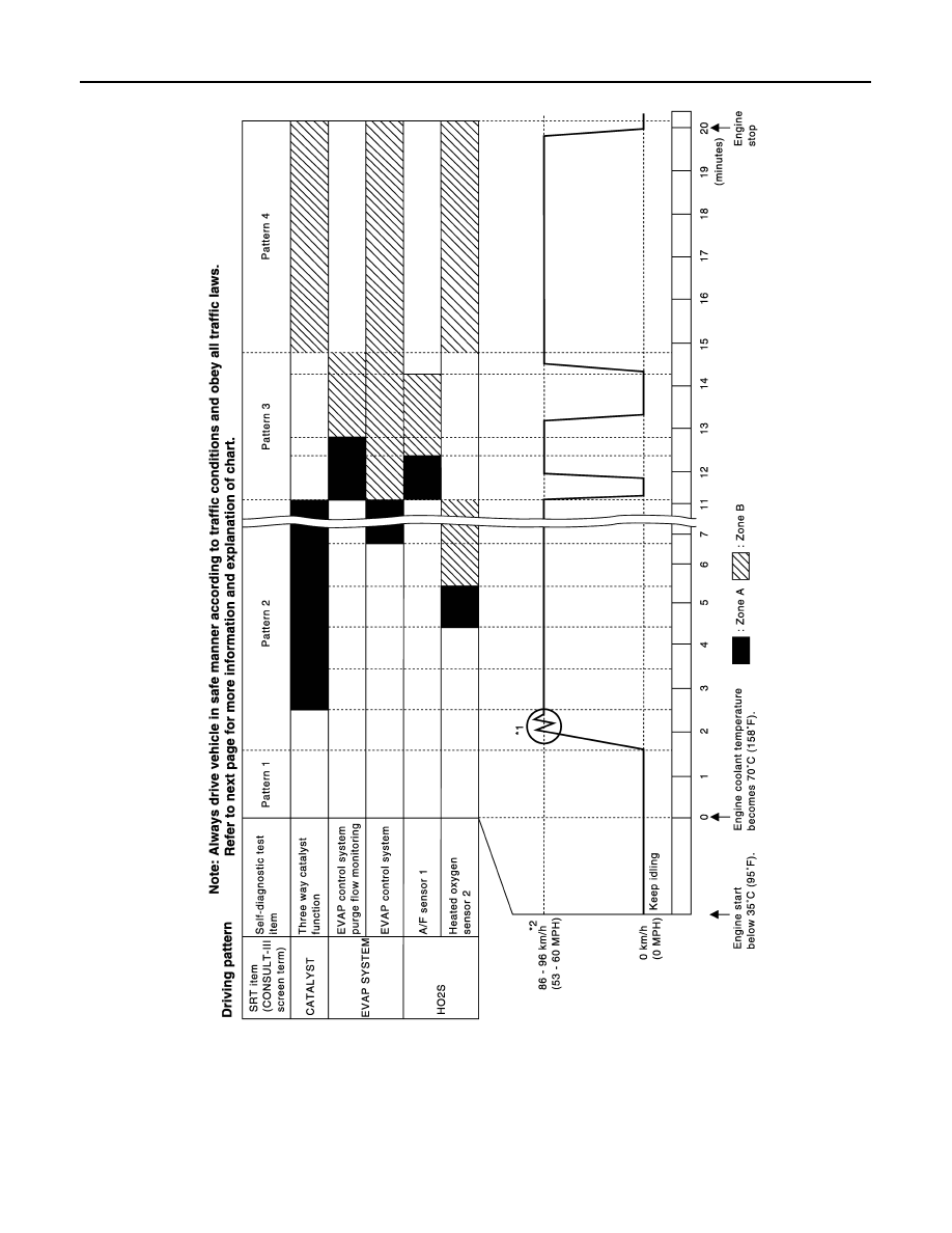
Driving Pattern
• The time required for each diagnosis varies with road surface conditions, weather, altitude, individual driving
habits, etc.
Zone A refers to the range where the time, required for the diagnosis under normal conditions*, is the short-
est.
Zone B refers to the range where the diagnosis can still be performed if the diagnosis is not completed within
zone A.
*: Normal conditions refer to the following:
PBIB3622E