Infiniti QX56 (JA60). Manual - part 444
EC-428
< ECU DIAGNOSIS >
[VK56DE]
ECM
21
22
23
44
O/L
BR
GR/W
O
Fuel injector No. 5
Fuel injector No. 3
Fuel injector No. 1
Fuel injector No. 7
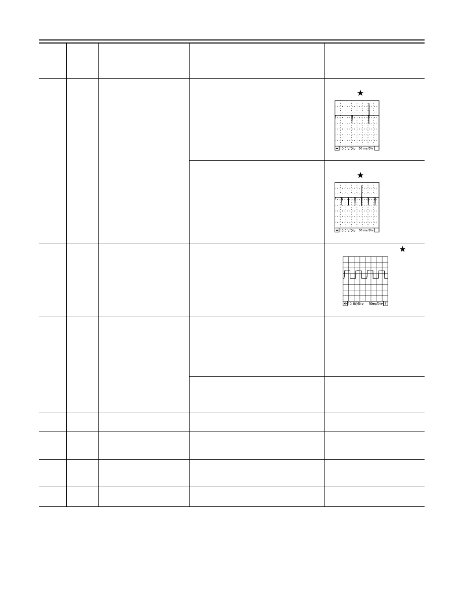
[Engine is running]
• Warm-up condition
• Idle speed
NOTE:
The pulse cycle changes depending on rpm at
idle
BATTERY VOLTAGE
(11 - 14V)
[Engine is running]
• Warm-up condition
• Engine speed: 2,000 rpm
BATTERY VOLTAGE
(11 - 14V)
24
43
GR/G
GR/G
A/F sensor 1 heater (bank 2)
[Engine is running]
• Warm-up condition
• Idle speed
(More than 140 seconds after starting en-
gine)
Approximately 2.9 - 8.8V
25
O/G
Heated oxygen sensor 2 heat-
er (bank 2)
[Engine is running]
• Engine speed: Below 3,600 rpm after the
following conditions are met.
- Engine: After warming up
- Keeping the engine speed between 3,500
and 4,000 rpm for 1 minute and at idle for 1
minute under no load
0 - 1.0V
[Ignition switch: ON]
• Engine: Stopped
[Engine is running]
• Engine speed: Above 3,600 rpm
BATTERY VOLTAGE
(11 - 14V)
32
L
EVAP control system pres-
sure sensor
[Ignition switch: ON]
Approximately 1.8 - 4.8V
34
R/B
Intake air temperature sensor
[Engine is running]
Approximately 0 - 4.8V
Output voltage varies with intake
air temperature.
35
O
A/F sensor 1 (bank 1)
[Engine is running]
• Warm-up condition
• Engine speed: 2,000 rpm
Approximately 1.8V
Output voltage varies with air fuel
ratio.
36
W
Knock sensor (bank 2)
[Engine is running]
• Idle speed
Approximately 2.5V
TER-
MI-
NAL
NO.
WIRE
COLOR
ITEM
CONDITION
DATA (DC Voltage)
SEC984C
SEC985C
PBIA8148J