Infiniti QX56 (JA60). Manual - part 383
EC-184
< COMPONENT DIAGNOSIS >
[VK56DE]
P0181 FTT SENSOR
>> Repair open circuit or short to power in harness or connector.
5.
CHECK FUEL TANK TEMPERATURE SENSOR
EC-184, "Component Inspection"
OK or NG
OK
>> GO TO 6.
NG
>> Replace “fuel level sensor unit and fuel pump”.
6.
CHECK INTERMITTENT INCIDENT
GI-35, "How to Check Terminal"
and
GI-38, "Intermittent Incident"
>> INSPECTION END
Component Inspection
INFOID:0000000005149200
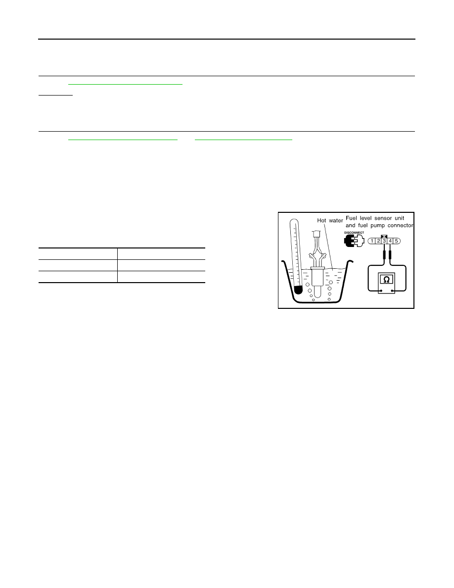
FUEL TANK TEMPERATURE SENSOR
1. Remove fuel level sensor unit.
2. Check resistance between “fuel level sensor unit and fuel pump”
terminals 3 and 4 by heating with hot water as shown in the fig-
ure.
If NG, replace fuel level sensor unit.
Temperature
°C (°F)]
Resistance (k
Ω)
20 (68)
2.3 - 2.7
50 (122)
0.79 - 0.90
SEF476YA