Infiniti QX56 (JA60). Manual - part 363


  Index      Infiniti     Infiniti QX56 (JA60) - service repair manual 2010 year


Search            


Content   ..  361  362  363  364   ..


Infiniti QX56 (JA60). Manual - part 363


EC-104

< COMPONENT DIAGNOSIS >

[VK56DE]

P0101 MAF SENSOR

P0101 MAF SENSOR

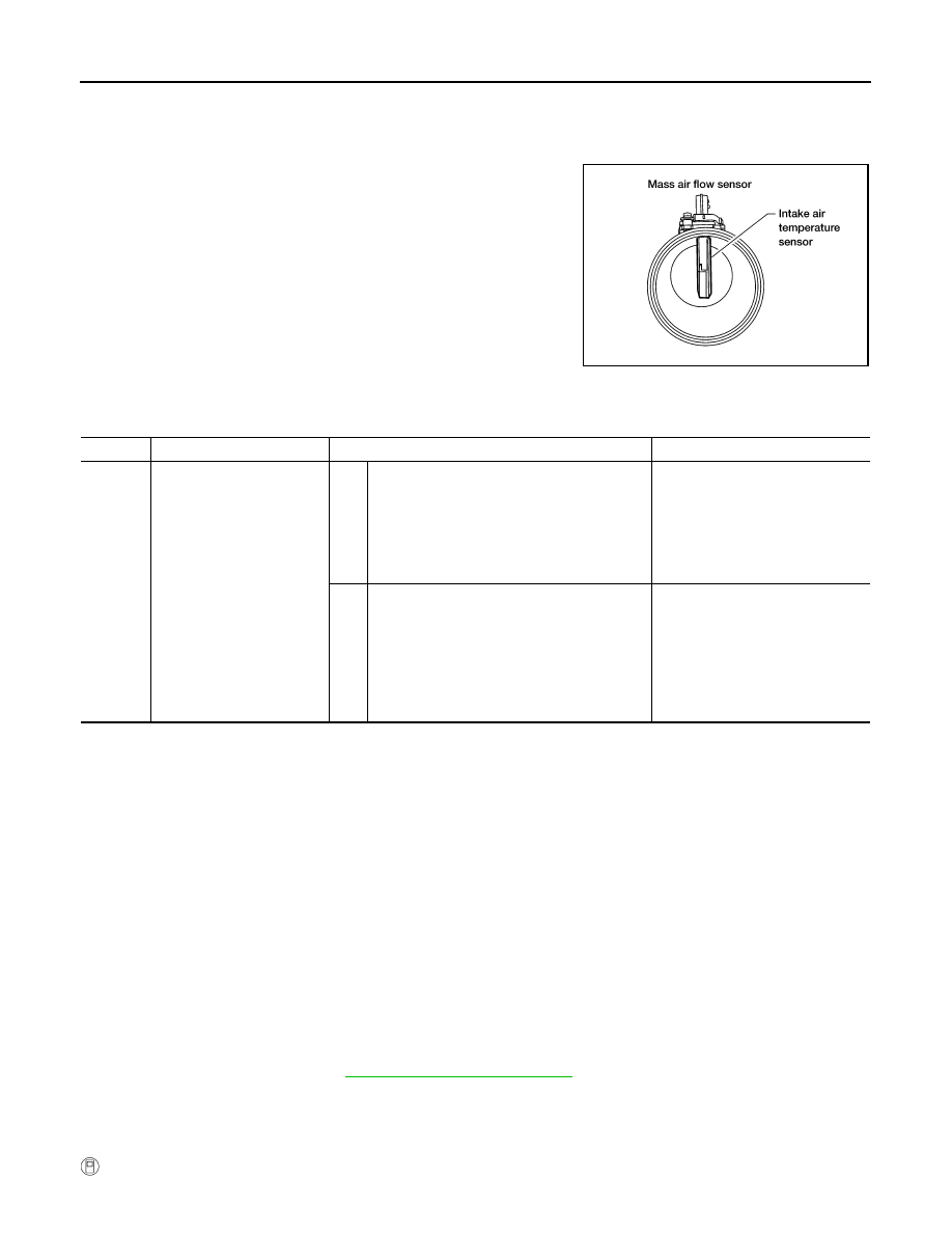
Component Description

INFOID:0000000005149110

The mass air flow sensor is placed in the stream of intake air. It mea-

sures the intake flow rate by measuring a part of the entire intake

flow. The mass air flow sensor controls the temperature of the hot

wire to a certain amount. The heat generated by the hot wire is

reduced as the intake air flows around it. The more air, the greater

the heat loss.

Therefore, the electric current supplied to the hot wire is changed to

maintain the temperature of the hot wire as air flow increases. The

ECM detects the air flow by means of this current change.

On Board Diagnosis Logic

INFOID:0000000005149111

DTC Confirmation Procedure

INFOID:0000000005149112

Perform PROCEDURE FOR MALFUNCTION A first.

If the DTC cannot be confirmed, perform PROCEDURE FOR MALFUNCTION B.

NOTE:

If DTC Confirmation Procedure has been previously conducted, always perform the following procedure

before conducting the next step.
1. Turn ignition switch OFF and wait at least 10 seconds.
2. Turn ignition switch ON.
3. Turn ignition switch OFF and wait at least 10 seconds.

PROCEDURE FOR MALFUNCTION A

NOTE:

If engine will not start or stops soon, wait at least 10 seconds with engine stopped (Ignition switch ON) instead

of running engine at idle speed.

1. Start engine and warm it up to normal operating temperature.

2. Run engine for at least 10 seconds at idle speed.

3. Check 1st trip DTC.

4. If 1st trip DTC is detected, go to 

EC-106, "Diagnosis Procedure"

.

PROCEDURE FOR MALFUNCTION B

CAUTION:

Always drive vehicle at a safe speed.

 With CONSULT-III 

BBIA0355E

DTC No.

Trouble diagnosis name

DTC detecting condition

Possible cause

P0101
0101

Mass air flow sensor circuit 
range/performance

A)

A high voltage from the sensor is sent to ECM 
under light load driving condition.

• Harness or connectors

(The sensor circuit is open or 
shorted.)

• Mass air flow sensor
• EVAP control system pressure 

sensor

• Intake air temperature sensor

B)

A low voltage from the sensor is sent to ECM 
under heavy load driving condition.

• Harness or connectors

(The sensor circuit is open or 
shorted.)

• Intake air leaks
• Mass air flow sensor
• EVAP control system pressure 

sensor

• Intake air temperature sensor

P0101 MAF SENSOR

EC-105

< COMPONENT DIAGNOSIS >

[VK56DE]

C

D

E

F

G

H

I

J

K

L

M

A

EC

N

P

O

1. Start engine and warm it up to normal operating temperature.

If engine cannot be started, go to 

EC-106, "Diagnosis Procedure"

.

2. Select “DATA MONITOR” mode with CONSULT-III.

3. Check the voltage of “MAS A/F SE-B1” with “DATA MONITOR”.

4. Increases engine speed to about 4,000 rpm.

5. Monitor the linear voltage rise in response to engine speed

increases.

If NG, go to 

EC-106, "Diagnosis Procedure"

.

If OK, go to following step.

6. Maintain the following conditions for at least 10 consecutive seconds.

7. Check 1st trip DTC.

8. If 1st trip DTC is detected, go to 

EC-106, "Diagnosis Procedure"

.

Overall Function Check

INFOID:0000000005149113

PROCEDURE FOR MALFUNCTION B

Use this procedure to check the overall function of the mass air flow sensor circuit. During this check, a 1st trip

DTC might not be confirmed.

 With GST

1. Start engine and warm it up to normal operating temperature.

2. Select Service $01 with GST.

3. Check the mass air flow sensor signal with Service $01.

4. Check for linear mass air flow sensor signal value rise in

response to increases to about 4,000 rpm in engine speed.

5. If NG, go to 

EC-106, "Diagnosis Procedure"

.

PBIB3457E

ENG SPEED

More than 2,000 rpm

TP SEN 1-B1

More than 1.5 V

TP SEN 2-B1

More than 1.5 V

Selector lever

Suitable position

Driving location

Driving vehicle uphill (Increased engine load) will help 
maintain the driving conditions required for this test.

SEF534P

EC-106

< COMPONENT DIAGNOSIS >

[VK56DE]

P0101 MAF SENSOR

Diagnosis Procedure

INFOID:0000000005149114

1.

INSPECTION START

Which malfunction (A or B) is duplicated?
A or B

A

>> GO  TO  3.

B

>> GO  TO  2.

2.

CHECK INTAKE SYSTEM

Check the following for connection.

• Air duct

• Vacuum hoses

• Intake air passage between air duct to intake manifold
OK or NG

OK

>> GO TO 3.

NG

>> Reconnect the parts.

3.

CHECK GROUND CONNECTIONS

1. Turn ignition switch OFF.

2. Loosen and retighten three ground screws on the body.

Refer to 

EC-85, "Ground Inspection"

.

OK or NG

OK

>> GO TO 4.

NG

>> Repair or replace ground connections.

4.

CHECK MAF SENSOR POWER SUPPLY CIRCUIT

1. Disconnect mass air flow (MAF) sensor harness connector.

2. Turn ignition switch ON.

BBIA0354E

BBIA0368E

P0101 MAF SENSOR

EC-107

< COMPONENT DIAGNOSIS >

[VK56DE]

C

D

E

F

G

H

I

J

K

L

M

A

EC

N

P

O

3. Check voltage between MAF sensor terminal 2 and ground with

CONSULT-III or tester.

OK or NG

OK

>> GO TO 6.

NG

>> GO TO 5.

5.

DETECT MALFUNCTIONING PART

Check the following.

• Harness connectors E2, F32

• Harness for open or short between IPDM E/R and mass air flow sensor

• Harness for open or short between mass air flow sensor and ECM

>> Repair harness or connectors.

6.

CHECK MAF SENSOR GROUND CIRCUIT FOR OPEN AND SHORT

1. Turn ignition switch OFF.

2. Disconnect ECM harness connector.

3. Check harness continuity between MAF sensor terminal 3 and ECM terminal 67.

Refer to Wiring Diagram.

4. Also check harness for short to ground and short to power.
OK or NG

OK

>> GO TO 7.

NG

>> Repair open circuit or short to ground or short to power in harness or connectors.

7.

CHECK MAF SENSOR INPUT SIGNAL CIRCUIT FOR OPEN AND SHORT

1. Check harness continuity between MAF sensor terminal 4 and ECM terminal 51.

Refer to Wiring Diagram.

2. Also check harness for short to ground and short to power.
OK or NG

OK

>> GO TO 8.

NG

>> Repair open circuit or short to ground or short to power in harness or connectors.

8.

CHECK INTAKE AIR TEMPERATURE SENSOR

Refer to 

EC-117, "Component Inspection"

.

OK or NG

OK

>> GO TO 9.

NG

>> Replace intake air temperature sensor.

9.

CHECK EVAP CONTROL SYSTEM PRESSURE SENSOR

Refer to 

EC-243, "Component Inspection"

.

OK or NG

OK

>> GO TO 10.

NG

>> Replace EVAP control system pressure sensor.

10.

CHECK MASS AIR FLOW SENSOR

Refer to 

EC-108, "Component Inspection"

.

OK or NG

Voltage: Battery voltage

PBIB1168E

Continuity should exist.

Continuity should exist.


Content   ..  361  362  363  364   ..