Infiniti QX56 (JA60). Manual - part 285
P1824 TRANSFER MOTOR
DLN-63
< COMPONENT DIAGNOSIS >
[ATX14B]
C
E
F
G
H
I
J
K
L
M
A
B
DLN
N
O
P
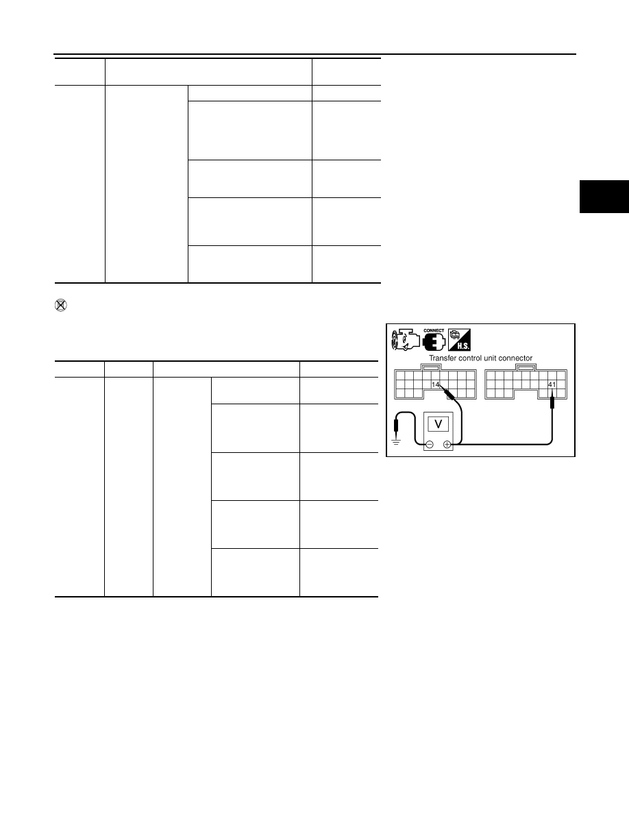
Without CONSULT-III
1. Start engine.
2. Check voltage between transfer control unit harness connector
terminal and ground.
MOTOR
RELAY
MON
• Accelerator ped-
al depressed
• Vehicle stopped
• Engine running
• Brake pedal de-
pressed
4WD shift switch: 2WD
OFF
4WD shift switch: AUTO or
4LO (A/T selector lever P or N
position)
OFF
(ON for approx.
2 sec. after
shifting to P and
N.)
4WD shift switch: AUTO or
4LO (Except for A/T selector
lever P or N position)
ON
4WD shift switch: 4H (A/T se-
lector lever P position)
OFF
(ON for approx.
2 sec. after
shifting to P.)
4WD shift switch: 4H (Except
for A/T selector lever P posi-
tion)
ON
Monitored
item
Condition
Display value
(Approx.)
Connector
Terminal
Condition
Voltage (Approx.)
E142
14 -
Ground
• Accelera-
tor pedal
depressed
• Vehicle
stopped
• Engine
running
• Brake
pedal de-
pressed
4WD shift switch:
2WD
Battery voltage
4WD shift switch:
AUTO or 4LO (A/T
selector lever P or N
position)
Battery voltage
(0V for approx. 2
sec. after shifting
to P and N.)
4WD shift switch:
AUTO or 4LO (Ex-
cept for A/T selector
lever P or N position)
0V
4WD shift switch: 4H
(A/T selector lever P
position)
Battery voltage
(0V for approx. 2
sec. after shifting
to P.)
4WD shift switch: 4H
(Except for A/T se-
lector lever P posi-
tion)
0V
SDIA2735E