Infiniti QX56 (JA60). Manual - part 277
P1810 NEUTRAL-4LO SWITCH
DLN-31
< COMPONENT DIAGNOSIS >
[ATX14B]
C
E
F
G
H
I
J
K
L
M
A
B
DLN
N
O
P
4. Push and release neutral-4LO switch and check continuity
between neutral-4LO switch terminals 12 and 13.
Are inspection results normal?
YES
>> GO TO 5.
NO
>> Replace neutral-4LO switch. Refer to
5.
CHECK TRANSFER CONTROL UNIT
Check transfer control unit input/output signal. Refer to
Are inspection results normal?
YES
>> GO TO 6.
NO
>> Check transfer control unit pin terminals for damage or loose connection with harness connector.
If any items are damaged, repair or replace damaged parts.
6.
CHECK DTC
Drive the vehicle and then perform self-diagnosis.
Are inspection results normal?
YES
>> Inspection End.
NO
>> Replace transfer control unit. Refer to
DLN-130, "Removal and Installation"
Component Inspection
INFOID:0000000005148791
1. Turn ignition switch OFF. (Stay for at least 5 seconds.)
2. Disconnect neutral-4LO switch harness connector.
3. Remove neutral-4LO switch. Refer to
DLN-16, "Component Parts Location"
.
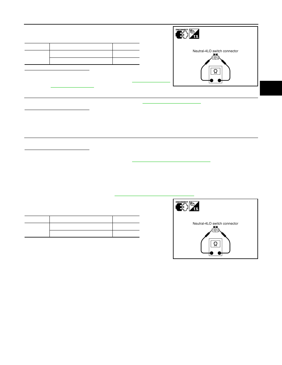
4. Push and release neutral-4LO switch and check continuity
between neutral-4LO switch terminals 12 and 13.
5. If the inspection results are abnormal replace the neutral-4LO
switch.
Terminal
Condition
Continuity
12 - 13
Push neutral-4LO switch
Yes
Release neutral-4LO switch
No
SDIA2696E
Terminal
Condition
Continuity
12 - 13
Push neutral-4LO switch
Yes
Release neutral-4LO switch
No
SDIA2696E