Infiniti QX56 (JA60). Manual - part 198
REAR WINDOW DEFOGGER RELAY
DEF-9
< COMPONENT DIAGNOSIS >
C
D
E
F
G
H
I
J
K
M
A
B
DEF
N
O
P
REAR WINDOW DEFOGGER RELAY
Description
INFOID:0000000005146827
Power is supplied to the rear window defogger with BCM control.
Component Function Check
INFOID:0000000005146828
1.
CHECK REAR WINDOW DEFOGGER RELAY POWER SUPPLY CIRCUIT
Check that an operation noise of rear window defogger relay (located in IPDM E/R) can be heard when turning
the rear window defogger switch ON.
Is the inspection result normal?
YES
>> Rear window defogger relay power supply circuit is OK.
NO
>> Refer to
.
Diagnosis Procedure
INFOID:0000000005146829
Regarding Wiring Diagram information, refer to
.
1.
CHECK FUSES
Check if any of the following fuses in the IPDM E/R are blown.
Is the inspection result normal?
YES
>> GO TO 2
NO
>> If fuse is blown, be sure to eliminate cause of malfunction before installing new fuse.
2.
CHECK REAR WINDOW DEFOGGER RELAY POWER SUPPLY CIRCUIT
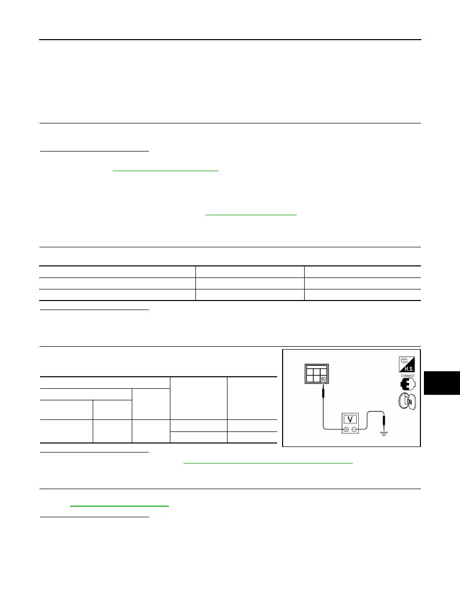
1. Turn ignition switch ON.
2. Check voltage between IPDM E/R connector and ground.
Is the inspection result normal?
YES
>> Replace IPDM E/R. Refer to
PCS-35, "Removal and Installation of IPDM E/R"
.
NO
>> GO TO 3
3.
CHECK INTERMITTENT INCIDENT
Check intermittent incident.
GI-38, "Intermittent Incident"
Is the inspection result normal?
YES
>> Check the following.
• Battery power supply circuit.
• IPDM E/R.
NO
>> Repair or replace the malfunctioning parts.
COMPONENT PARTS
AMPERE
FUSE NO.
IPDM E/R
15A
46
IPDM E/R
15A
47
Terminals
Condition of rear
window defogger
switch
Voltage (V)
(Approx.)
(+)
(–)
IPDM E/R con-
nector
Terminal
E124
60
Ground
ON Battery
voltage
OFF
0
LIIA2190E