Infiniti QX56 (JA60). Manual - part 187
CHG
B TERMINAL CIRCUIT
CHG-11
< COMPONENT DIAGNOSIS >
C
D
E
F
G
H
I
J
K
L
B
A
O
P
N
B TERMINAL CIRCUIT
Description
INFOID:0000000005146559
The terminal “1” circuit supplies power to charge the battery and operate the vehicles electrical system.
Diagnosis Procedure
INFOID:0000000005146560
Regarding Wiring Diagram information, refer to
1.
CHECK TERMINAL “1” CONNECTION
1. Turn ignition switch OFF.
2. Verify terminal “1” is clean and tight.
Is the inspection result normal?
YES
>> GO TO 2.
NO
>> Repair terminal “1” connection. Confirm repair by performing complete Starting/Charging system
test. Refer to diagnostic station instruction manual.
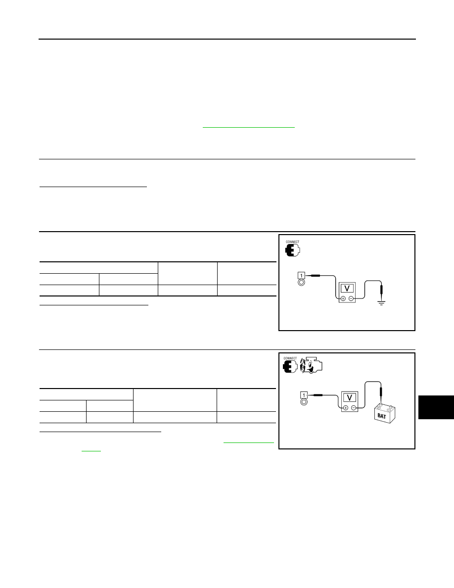
2.
CHECK TERMINAL “1” CIRCUIT
Check voltage between generator connector E204 terminal 1 and
ground.
Is voltage reading as specified?
YES
>> GO TO 3.
NO
>> Check harness for open between generator and fusible
link.
3.
CHECK TERMINAL “1” CONNECTION (VOLTAGE DROP TEST)
1. Start engine, then engine running at idle and warm.
2. Check voltage between battery positive terminal and generator
connector E204 terminal 1.
Is the voltage reading as specified?
YES
>> Terminal “1” circuit is normal. Refer to
NO
>> Check harness between battery and generator for high resistance.
(+)
(-)
Voltage
Connector
Terminal
E204
1
Ground
Battery voltage
ALMIA0197ZZ
(+)
(-)
Voltage
Connector
Terminal
E204
1
Battery positive terminal
Less than 0.2V
ALMIA0198ZZ