Infiniti QX56 (JA60). Manual - part 139


  Index      Infiniti     Infiniti QX56 (JA60) - service repair manual 2010 year


Search            


Content   ..  137  138  139  140   ..


Infiniti QX56 (JA60). Manual - part 139


C1164, C1165, C1166, C1167 CV/SV SYSTEM

BRC-69

< COMPONENT DIAGNOSIS >

[VDC/TCS/ABS]

C

D

E

G

H

I

J

K

L

M

A

B

BRC

N

O

P

C1164, C1165, C1166, C1167 CV/SV SYSTEM

Description

INFOID:0000000005148042

CV1, CV2 (CUT VALVE)

The cut valve shuts off the normal brake fluid path from the master cylinder, when VDC/TCS is activated.

SV1, SV2 (SUCTION VALVE)

The suction valve supplies the brake fluid from the master cylinder to the pump, when VDC/TCS is activated.

DTC Logic

INFOID:0000000005148043

DTC DETECTION LOGIC

DTC CONFIRMATION PROCEDURE

1.

CHECK SELF-DIAGNOSIS RESULTS

Check the self-diagnosis results.

Is above displayed on the self-diagnosis display?

YES

>> Proceed to diagnosis procedure. Refer to 

BRC-69, "Diagnosis Procedure"

.

NO

>> Inspection End

Diagnosis Procedure

INFOID:0000000005194933

Regarding Wiring Diagram information, refer to 

BRC-92, "Wiring Diagram - BRAKE CONTROL SYSTEM -"

.

1.

CONNECTOR INSPECTION

1. Turn ignition switch OFF.

2. Disconnect ABS actuator and electric unit (control unit) connector.

3. Check terminal for deformation, disconnection, looseness, and so on. If any malfunction is found, repair or

replace terminal.

4. Reconnect connectors and then perform the self-diagnosis. Refer to 

BRC-23, "CONSULT-III Function

(ABS)"

.

Is any item indicated on the self-diagnosis display?
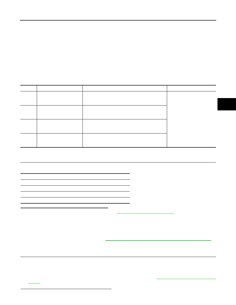
DTC

Display item

Malfunction detected condition

Possible cause

C1164

CV1

VDC switch-over solenoid valve (CV1) on the primary 
side is open circuit or shorted, or the control line is open 
or shorted to the power supply or the ground.

• Harness or connector
• ABS actuator and electric unit 

(control unit)

C1165

CV2

VDC switch-over solenoid valve (CV2) on the primary 
side is open circuit or shorted, or the control line is open 
or shorted to the power supply or the ground.

C1166

SV1

VDC switch-over solenoid valve (SV1) on the primary 
side is open circuit or shorted, or the control line is open 
or shorted to the power supply or the ground.

C1167

SV2

VDC switch-over solenoid valve (SV2) on the primary 
side is open circuit or shorted, or the control line is open 
or shorted to the power supply or the ground.

Self-diagnosis results

CV1

CV2

SV1

SV2

BRC-70

< COMPONENT DIAGNOSIS >

[VDC/TCS/ABS]

C1164, C1165, C1166, C1167 CV/SV SYSTEM

YES

>> GO TO 2

NO

>> Poor connection of connector terminal. Repair or replace connector.

2.

CHECK SOLENOID, VDC SWITCH-OVER VALVE AND ACTUATOR RELAY POWER SUPPLY CIRCUIT

1. Turn ignition switch OFF.

2. Disconnect ABS actuator and electric unit (control unit) connec-

tor.

3. Check voltage between ABS actuator and electric unit (control

unit) connector E125 terminal 32 and ground.

Is the inspection result normal?

YES

>> GO TO 3

NO

>> Repair or replace malfunctioning components.

3.

CHECK SOLENOID, VDC SWITCH-OVER VALVE AND ACTUATOR RELAY GROUND CIRCUIT

Check continuity between ABS actuator and electric unit (control

unit) connector E125 terminals 16, 47 and ground.

Is the inspection result normal?

YES

>> Replace ABS actuator and electric unit (control unit).

Refer to 

BRC-116, "Removal and Installation"

.

NO

>> Repair or replace malfunctioning components.

Component Inspection

INFOID:0000000005148045

1.

CHECK ACTIVE TEST

1. Select each test menu item on “ACTIVE TEST”.

2. On the display, touch “Up”, “ACT UP”, and “ACT KEEP”, and check that the system operates as shown in

the table below.

ABS actuator and electric unit (control unit)

Voltage

Connector

Terminal

E125

32

Ground

Battery voltage

AWFIA0018ZZ

ABS actuator and electric unit (control unit)

Continuity

Connector

Terminal

E125

16, 47

Ground

Yes

AWFIA0016ZZ

Operation

ABS solenoid valve (ACT)

Up

ACT UP

ACT KEEP

FR RH ABS SOLENOID (ACT)

FR RH IN SOL

Off

Off

Off

FR RH OUT SOL

Off

Off

Off

CV1

Off

On

On

SV1

Off

On*

Off

FR LH ABS SOLENOID (ACT)

FR LH IN SOL

Off

Off

Off

FR LH OUT SOL

Off

Off

Off

CV1

Off

On

On

SV1

Off

On*

Off

RR RH ABS SOLENOID (ACT)

RR RH IN SOL

Off

Off

Off

RR RH OUT SOL

Off

Off

Off

CV2

Off

On

On

SV2

Off

On*

Off

C1164, C1165, C1166, C1167 CV/SV SYSTEM

BRC-71

< COMPONENT DIAGNOSIS >

[VDC/TCS/ABS]

C

D

E

G

H

I

J

K

L

M

A

B

BRC

N

O

P

*: On for 1 to 2 seconds after the touch, and then Off

Is the inspection result normal?

YES

>> Inspection End

NO

>> Go to diagnosis procedure. Refer to 

BRC-69, "Diagnosis Procedure"

.

Special Repair Requirement

INFOID:0000000005194920

1.

ADJUSTMENT OF STEERING ANGLE SENSOR NEUTRAL POSITION

Always perform neutral position adjustment for the steering angle sensor when replacing the ABS actuator

and electric unit (control unit). Refer to 

BRC-8, "ADJUSTMENT OF STEERING ANGLE SENSOR NEUTRAL

POSITION : Description"

.

>> GO TO 2

2.

CALIBRATION OF DECEL G SENSOR

Always perform calibration of decel G sensor when replacing the ABS actuator and electric unit (control unit).

Refer to 

BRC-9, "CALIBRATION OF DECEL G SENSOR : Description"

.

>> END

RR LH ABS SOLENOID (ACT)

RR LH IN SOL

Off

Off

Off

RR LH OUT SOL

Off

Off

Off

CV2

Off

On

On

SV2

Off

On*

Off

Operation

ABS solenoid valve (ACT)

Up

ACT UP

ACT KEEP

BRC-72

< COMPONENT DIAGNOSIS >

[VDC/TCS/ABS]

C1178, C1181, C1184, C1189 ABS ACTIVE BOOSTER

C1178, C1181, C1184, C1189 ABS ACTIVE BOOSTER

Description

INFOID:0000000005148047

The active brake booster consists of a vacuum booster, an active booster control group and a delta stroke

sensor. If a brake booster system malfunction occurs due to loss of vacuum, the delta stroke sensor will signal

the ABS actuator and electric unit (control unit) that a booster malfunction has occurred. The active booster

then applies supplemental force to the master cylinder relative to the amount of force exerted on the brake

pedal.

DTC Logic

INFOID:0000000005148048

DTC DETECTION LOGIC

DTC CONFIRMATION PROCEDURE

1.

CHECK SELF-DIAGNOSIS RESULTS

Check the self-diagnosis results.

Is above displayed on the self-diagnosis display?

YES

>> Proceed to diagnosis procedure. Refer to 

BRC-72, "Diagnosis Procedure"

.

NO

>> Inspection End

Diagnosis Procedure

INFOID:0000000005148049

Regarding Wiring Diagram information, refer to 

BRC-92, "Wiring Diagram - BRAKE CONTROL SYSTEM -"

.

1.

CONNECTOR INSPECTION

1. Turn the ignition switch OFF.

2. Disconnect the active booster connector and ABS actuator and electric unit (control unit) connector and

inspect the terminals for deformation, disconnection, looseness, or damage.

Is the inspection result normal?

YES

>> GO TO 2

NO

>> Repair connector.

2.

ACTIVE BOOSTER CIRCUIT INSPECTION

DTC

Display item

Malfunction detected condition

Possible cause

C1178

ABS ACTIVE BOOSTER SV 
NG

Active booster solenoid is malfunctioning, or signal line of 
active booster servo is open or shorted.

• Harness or connector
• Active booster
• ABS actuator and electric unit 

(control unit)

C1181

ABS ACTIVE BOOSTER RE-
SPONSE NG

Active booster response is malfunctioning, or signal line 
of active booster response is open or shorted.

C1184

ABS BRAKE RELEASE SW 
NG

Brake release switch is malfunctioning, or signal line of 
brake release switch is open or shorted.

C1189

ABS BRAKE BOOSTER DE-
FECT

Brake booster is defective or malfunctioning.

Self-diagnosis results

ABS ACTIVE BOOSTER SV NG

ABS ACTIVE BOOSTER RESPONSE NG

ABS BRAKE RELEASE SW NG

ABS BRAKE BOOSTER DEFECT


Content   ..  137  138  139  140   ..