Infiniti QX56 (JA60). Manual - part 110
BCS
BCM (BODY CONTROL MODULE)
BCS-59
< ON-VEHICLE REPAIR >
[BCM]
C
D
E
F
G
H
I
J
K
L
B
A
O
P
N
ON-VEHICLE REPAIR
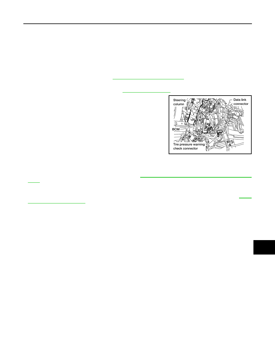
BCM (BODY CONTROL MODULE)
Removal and Installation
INFOID:0000000005146436
REMOVAL
NOTE:
If possible, before removing BCM, retrieve current BCM configuration to use for reference when configuring
brand-new BCM after installation. Refer to
WT-6, "ID Registration Procedure"
.
1. Disconnect the battery negative terminal.
2. Remove the lower knee protector. Refer to
.
3. Remove the screw and release the BCM.
4. Disconnect the connectors and then remove the BCM.
INSTALLATION
Installation is in the reverse order of removal.
NOTE:
• When replacing BCM, it must be configured. Refer to
BCS-4, "CONFIGURATION : Special Repair Require-
.
• When replacing BCM, perform initialization of NATS system and registration of all NATS ignition key IDs.
Refer to the CONSULT-III operation manual for the initialization procedure.
• When replacing BCM, perform ID registration procedure of low tire pressure warning system. Refer to
LEIA0068E