Infiniti QX56 (JA60). Manual - part 73


  Index      Infiniti     Infiniti QX56 (JA60) - service repair manual 2010 year


Search            


Content   ..  71  72  73  74   ..


Infiniti QX56 (JA60). Manual - part 73


AV-100

< COMPONENT DIAGNOSIS >

[AUDIO SYSTEM]

BACK DOOR SPEAKER

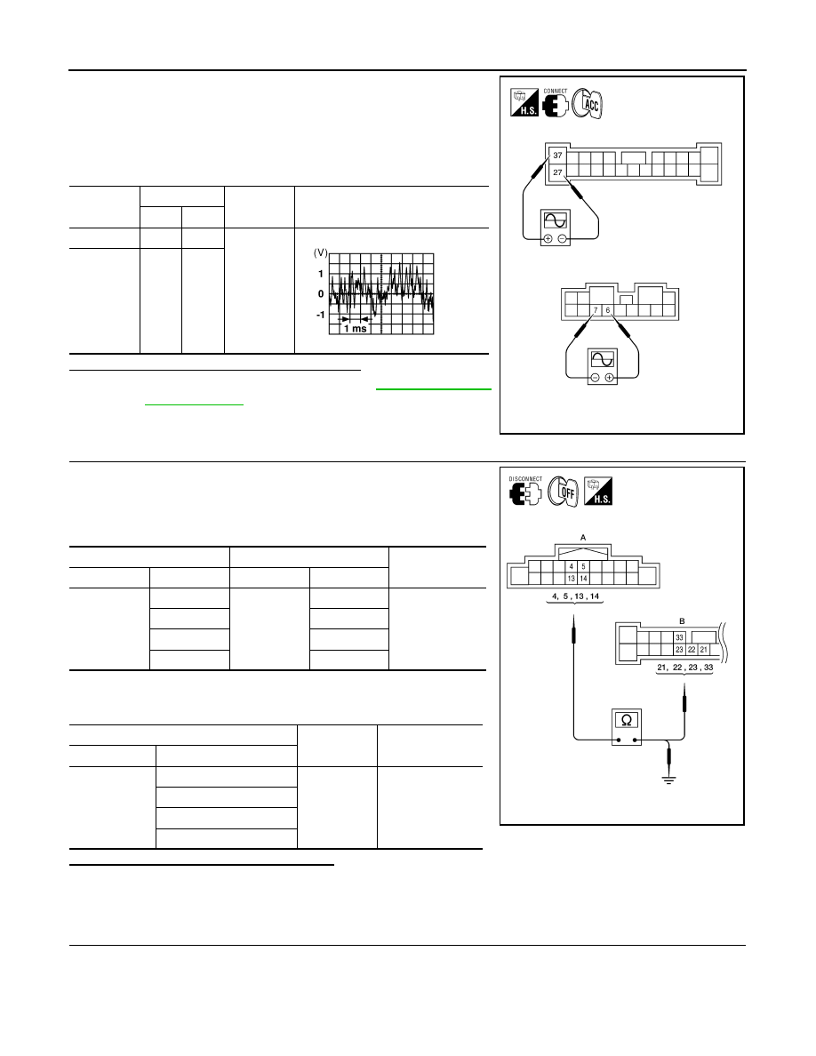
1. Connect BOSE speaker amp. connectors and suspect speaker

connector.

2. Turn ignition switch to ACC.

3. Push “POWER” switch.

4. Check the signal between BOSE speaker amp. harness connec-

tors M113 terminals with CONSULT-III or oscilloscope.

Are audio signal voltage readings as specified?

YES

>> Replace suspect speaker. Refer to 

AV-176, "Removal

and Installation"

.

NO

>> GO TO 3.

3.

HARNESS CHECK

1. Disconnect AV control unit connector M42 and BOSE speaker

amp. connector M113.

2. Check continuity between AV control unit harness connector

M42 (A) and BOSE speaker amp. harness connector M113 (B).

3. Check continuity between AV control unit harness connector

M42 (A) and ground.

Are the continuity test results as specified?

YES

>> GO TO 4.

NO

>> • Check connector housings for disconnected or loose terminals.

• Repair harness or connector.

4.

REAR DOOR SPEAKER SIGNAL CHECK

Connector

Terminals

Condition

Reference

signal

(+)

(-)

M112

6

7

Receive 
audio sig-
nal

M113

37

27

ALNIA0664GB

SKIA0177E

A

Continuity

Connector

Terminal

Connector

Terminal

M42

4

M113

21

Yes

5

22

13

23

14

33

A

Continuity

Connector

Terminal

M42

4

Ground

No

5

13

14

ALNIA0418GB

AV

BACK DOOR SPEAKER

AV-101

< COMPONENT DIAGNOSIS >

[AUDIO SYSTEM]

C

D

E

F

G

H

I

J

K

L

M

B

A

O

P

1. Connect AV control unit connector M42 and BOSE speaker

amp. connector M113.

2. Turn ignition switch to ACC.

3. Push “POWER” switch.

4. Check the signal between AV control unit harness connector

M42 terminals with CONSULT-III or oscilloscope.

Is the audio signal voltage reading as specified?

YES

>> Replace BOSE speaker amp. Refer to 

AV-182,

"Removal and Installation"

.

NO

>> Replace AV control unit. Refer to 

AV-169, "Removal and

Installation"

.

Connector

Terminals

Condition

Reference

signal

(+)

(-)

M42

4

5

Receive 
audio sig-
nal

13

14

ALNIA0419GB

SKIA0177E

AV-102

< COMPONENT DIAGNOSIS >

[AUDIO SYSTEM]

SUBWOOFER

SUBWOOFER

Description

INFOID:0000000005146337

The AV control unit sends audio signals to the BOSE speaker amp. The BOSE speaker amp. amplifies the

audio signals before sending them to the subwoofer using the audio signal circuits.

Diagnosis Procedure

INFOID:0000000005146338

Regarding Wiring Diagram information, refer to 

AV-116, "Wiring Diagram"

.

1.

VERIFY SUBWOOFER POWER AND GROUND SUPPLY

Check power and ground supply to the subwoofer.  Refer to 

AV-71, "WOOFER : Diagnosis Procedure"

Did the power and ground supply check OK?

YES

>> GO TO 2.

NO

>> • Check connector housings for disconnected or loose terminals.

• Repair harness or connector.

2.

HARNESS CHECK

1. Disconnect BOSE speaker amp. connector M112 and sub-

woofer connector.

2. Check continuity between BOSE speaker amp. harness connec-

tor M112 (A) and M113 (B) and subwoofer harness connector

B72 (C).

3. Check continuity between BOSE speaker amp. harness connec-

tor M112 (A) and M113 (B) and ground.

Are the continuity test results as specified?

YES

>> GO TO 3.

NO

>> • Check connector housings for disconnected or loose

terminals.

• Repair harness or connector.

3.

SUBWOOFER AMP ON SIGNAL CHECK

Connector

Terminal

Connector

Terminal

Continuity

A: M112

9

C: B72

2

Yes

14

1

B: M113

25

4

Connector

Terminal

-

Continuity

A: M112

9

Ground

No

14

B: M113

25

ALNIA0365GB

AV

SUBWOOFER

AV-103

< COMPONENT DIAGNOSIS >

[AUDIO SYSTEM]

C

D

E

F

G

H

I

J

K

L

M

B

A

O

P

1. Connect BOSE speaker amp. connector M112.

2. Turn ignition switch to ACC.

3. Push “POWER” switch. 

4. Check voltage between subwoofer connector B72 terminal 4

and ground.

Are the voltage test results as specified?

YES

>> GO TO 4.

NO

>> Replace BOSE speaker amp.  Refer to 

AV-182, "Removal and Installation"

.

4.

SUBWOOFER AUDIO SIGNAL CHECK

1. Connect BOSE speaker amp. connector M112 and subwoofer connector B72.

2. Turn ignition switch to ACC.

3. Push “POWER” switch.

4. Check the signal between BOSE speaker amp. harness connec-

tor M112 terminals with CONSULT-III or oscilloscope.

Is the audio signal voltage as specified?

YES

>> Replace subwoofer. Refer to 

AV-177, "Removal and Installation"

.

NO

>> GO TO 5.

5.

HARNESS CHECK

(+)

(-)

ACC

Connector

Terminal

B72

4

Ground

Battery voltage

ALNIA0364GB

Connector

Terminals

Condition

Reference

signal

(+)

(-)

M112

9

14

Receive au-
dio signal

ALNIA0366GB

SKIA0177E


Content   ..  71  72  73  74   ..