Infiniti QX56 (JA60). Manual - part 65
AV-68
< COMPONENT DIAGNOSIS >
[AUDIO SYSTEM]
POWER SUPPLY AND GROUND CIRCUIT
POWER SUPPLY AND GROUND CIRCUIT
AV CONTROL UNIT
AV CONTROL UNIT : Diagnosis Procedure
INFOID:0000000005146301
Regarding Wiring Diagram information, refer to
.
1.
CHECK FUSES
Check that the following AV control unit fuses are not blown.
Are the fuses OK?
YES
>> GO TO 2.
NO
>> If fuse is blown, be sure to eliminate cause of malfunction before installing new fuse.
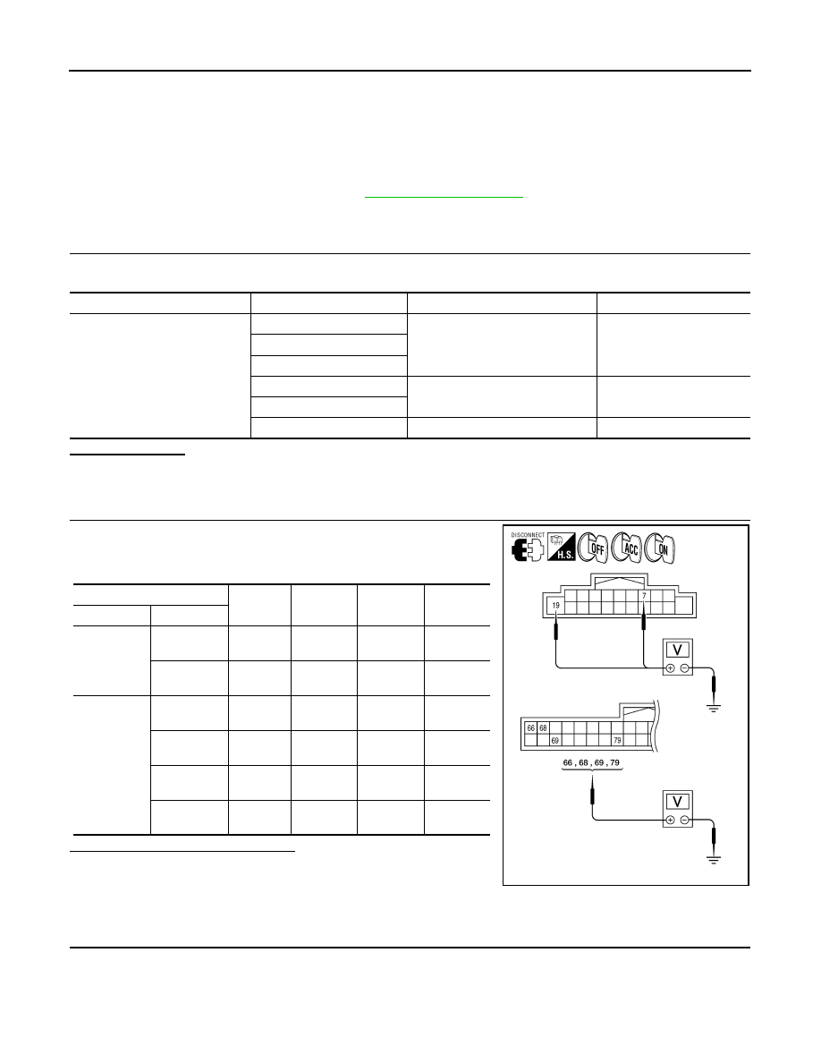
2.
POWER SUPPLY CIRCUIT CHECK
1. Disconnect AV control unit connectors M42 and M45.
2. Check voltage between the AV control unit connectors M42 and
M45 and ground.
Are the voltage results as specified?
YES
>> GO TO 3.
NO
>> • Check connector housings for disconnected or loose
terminals.
• Repair harness or connector.
3.
GROUND CIRCUIT CHECK
Unit
Terminals
Signal name
Fuse No.
AV control unit
19
Battery power
31
66
68
7
Ignition switch ACC or ON
4
69
79
Ignition switch ON or START
12
(+)
(-)
OFF
ACC
ON
Connector
Terminal
M42
7
Ground
0V
Battery
voltage
Battery
voltage
19
Ground
Battery
voltage
Battery
voltage
Battery
voltage
M45
66
Ground
Battery
voltage
Battery
voltage
Battery
voltage
68
Ground
Battery
voltage
Battery
voltage
Battery
voltage
69
Ground
0V
Battery
voltage
Battery
voltage
79
Ground
0V
0V
Battery
voltage
AWNIA1554ZZ