Infiniti QX56 (JA60). Manual - part 30
DOOR MIRROR MOTOR
ADP-111
< COMPONENT DIAGNOSIS >
C
D
E
F
G
H
I
K
L
M
A
B
ADP
N
O
P
Door mirror RH
Is the inspection result normal?
YES
>> GO TO 4
NO
>> Replace automatic drive positioner control unit. Refer to
ADP-175, "Removal and Installation"
.
4.
CHECK DOOR MIRROR MOTOR
Check door mirror motor.
ADP-111, "Component Inspection"
Is the inspection result normal?
YES
>> Refer to
GI-38, "Intermittent Incident"
.
NO
>> Replace door mirror actuator. Refer to
.
Component Inspection
INFOID:0000000005147571
1.
CHECK DOOR MIRROR MOTOR-I
Check that door mirror motor does not trap foreign objects and does not have any damage.
MIR-17, "Door Mirror Assembly"
Is the inspection result normal?
YES
>> GO TO 2
NO
>> Replace door mirror actuator. Refer to
.
2.
CHECK DOOR MIRROR MOTOR-II
1. Turn ignition switch OFF.
2. Disconnect door mirror.
3. Apply 12V to each power supply terminal of door mirror motor.
Is the inspection result normal?
YES
>> Inspection End.
NO
>> Replace door mirror actuator. Refer to
.
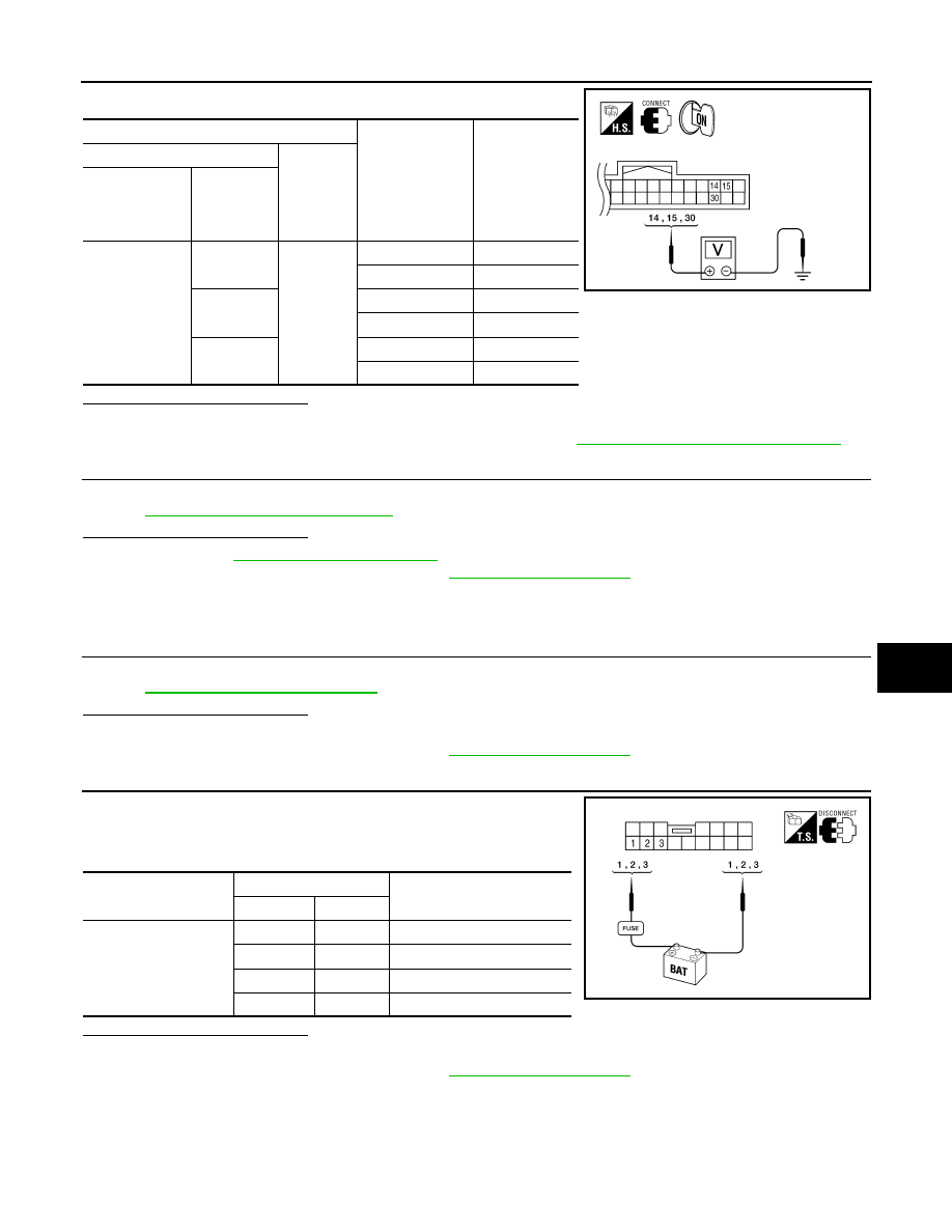
Terminals
Mirror switch con-
dition
Voltage (V)
(Approx.)
(+)
(-)
Automatic drive
positioner con-
trol unit connec-
tor
Terminal
M33
14
Ground
UP
Battery voltage
Other than above
0
15
LEFT
Battery voltage
Other than above
0
30
DOWN / RIGHT
Battery voltage
Other than above
0
ALJIA0198ZZ
Door mirror connector
Terminal
Operational direction
(+)
(–)
D4 (LH)
D107 (RH)
3
2
RIGHT
2
3
LEFT
1
3
UP
3
1
DOWN
ALJIA0199ZZ