Infiniti QX56 (JA60). Manual - part 13
B2126 DETENT SW
ADP-43
< COMPONENT DIAGNOSIS >
C
D
E
F
G
H
I
K
L
M
A
B
ADP
N
O
P
NO
>> GO TO 3
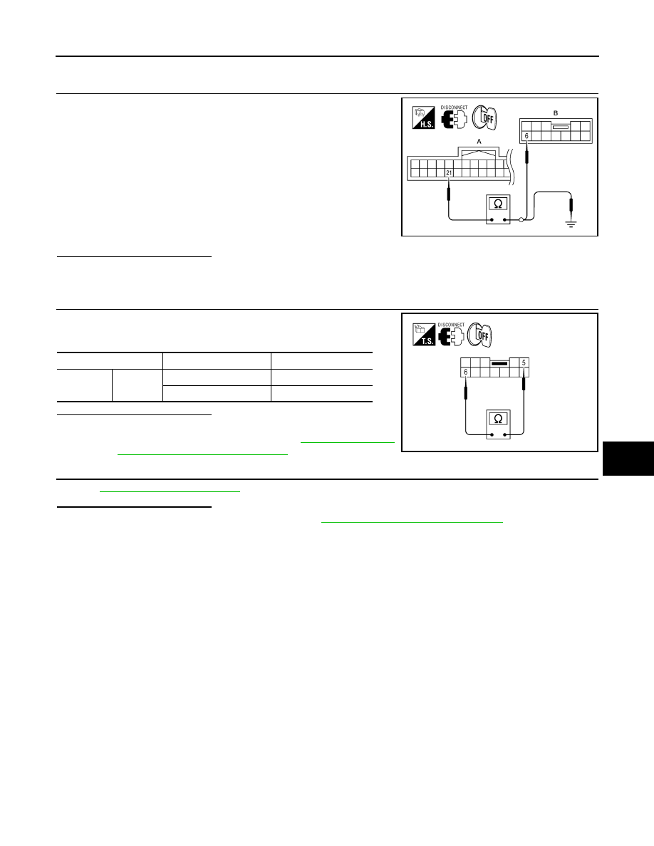
3.
CHECK A/T SHIFT SELECTOR (PARK POSITION SWITCH) HARNESS
1. Turn ignition switch OFF.
2. Disconnect A/T shift selector and driver seat control unit.
3. Check continuity between driver seat control unit connector
B202 (A) terminal 21 and A/T shift selector connector M203 (B)
terminal 6.
4. Check continuity between driver seat control unit connector
B202 (A) terminal 21 and ground.
Is the inspection result normal?
YES
>> GO TO 4
NO
>> Repair or replace harness.
4.
CHECK PARK POSITION SWITCH
Check continuity between A/T shift selector (park position switch)
terminals as follows.
Is the inspection result normal?
YES
>> GO TO 5
NO
>> Replace A/T shift selector. Refer to
Selector Removal and Installation"
.
5.
CHECK INTERMITTENT INCIDENT
GI-38, "Intermittent Incident"
.
Is the inspection result normal?
YES
>> Replace driver seat control unit. Refer to
ADP-174, "Removal and Installation"
NO
>> Repair or replace the malfunctioning part.
6 - 21
: Continuity should exist.
21 - Ground
: Continuity should not exist.
ALJIA0194ZZ
Terminals
Condition
Continuity
5
6
P position
Yes
Other than P position
No
ALJIA0486ZZ