Infiniti QX56 (JA60). Manual - part 6


  Index      Infiniti     Infiniti QX56 (JA60) - service repair manual 2010 year


Search            


Content   ..  4  5  6  7   ..


Infiniti QX56 (JA60). Manual - part 6


AUTOMATIC DRIVE POSITIONER SYSTEM

ADP-15

< FUNCTION DIAGNOSIS >

C

D

E

F

G

H

I

K

L

M

A

B

ADP

N

O

P

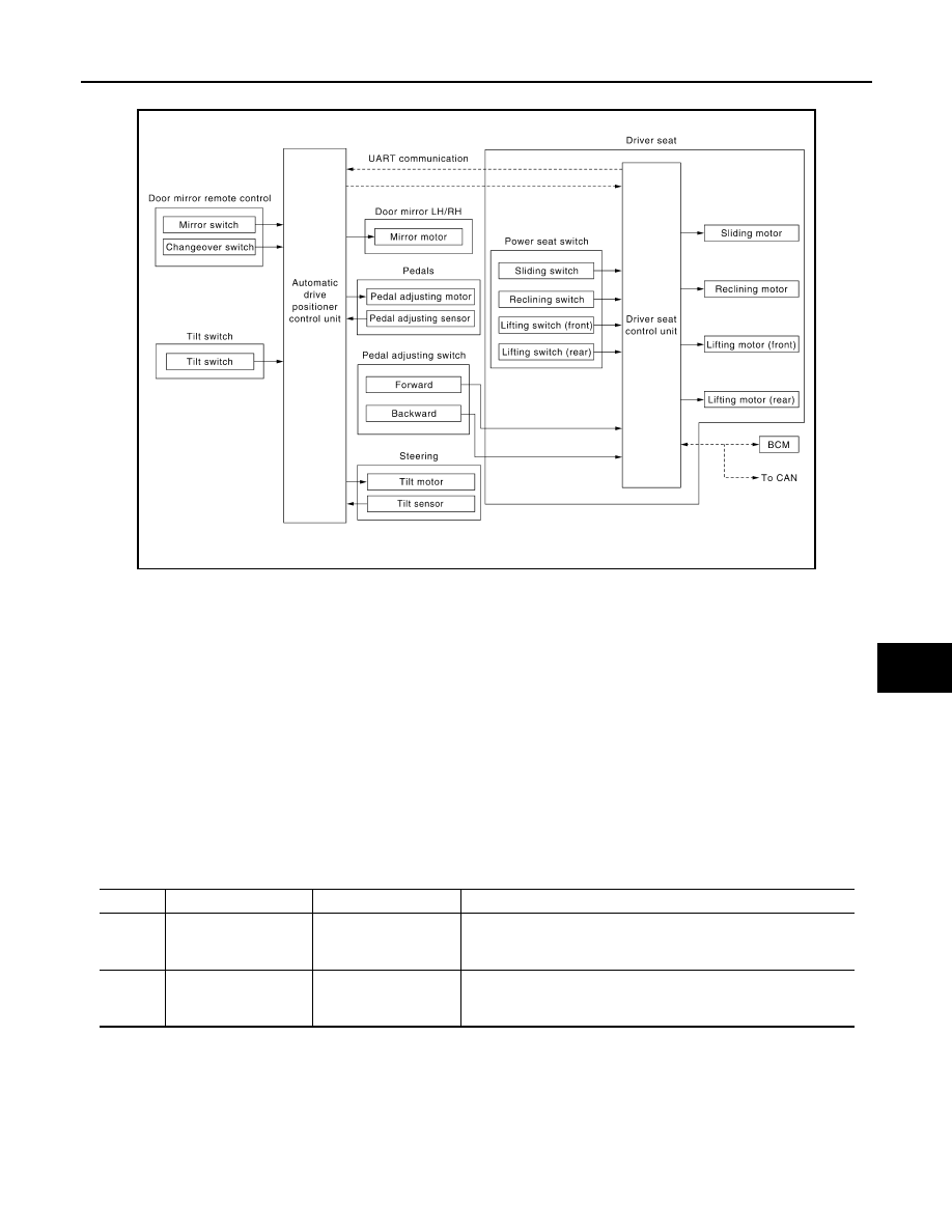
MANUAL FUNCTION : System Diagram

INFOID:0000000005147429

MANUAL FUNCTION : System Description

INFOID:0000000005147430

OUTLINE

The driving position (seat, pedal assembly, steering wheel and door mirror position) can be adjusted manually

with power seat switch, pedal adjusting switch, ADP steering switch and door mirror remote control switch.

OPERATION PROCEDURE

1. Turn ignition switch ON.

2. Operate power seat switch, pedal adjusting switch, ADP steering switch or door mirror remote control

switch.

3. The driver seat, pedal assembly, steering wheel or door mirror operates according to the operation of

each switch.

DETAIL FLOW

Seat

Adjustable pedals

ALJIA0236GB

Order

Input

Output

Control unit condition

1

Power seat switch
(sliding, lifting, reclin-
ing)

The power seat switch signal is inputted to the driver seat control 
unit when the power seat switch is operated.

2

Motors
(sliding, lifting, reclin-
ing)

The driver seat control unit outputs signals to each motor accord-
ing to the power seat switch input signal.

ADP-16

< FUNCTION DIAGNOSIS >

AUTOMATIC DRIVE POSITIONER SYSTEM

Tilt steering wheel

Door Mirror

NOTE:

The door mirrors can be operated manually when ignition switch is in either ACC or ON position. The ignition

switch signal (ACC/ON) is transmitted from BCM to the driver seat control unit via CAN communication and

from the driver seat control unit to the automatic drive positioner control unit via UART communication.

Order

Input

Output

Control unit condition

1

Pedal adjusting switch

The pedal adjusting switch signal is input to the automatic drive 
positioner control unit when the pedal adjusting switch is operat-
ed.

2

Motor

The automatic drive positioner control unit actuates the motor ac-
cording to the operation of the pedal adjusting switch signal from 
the driver seat control unit.

3

Sensor
(forward, backward)

The automatic drive positioner control unit recognizes any oper-
ation limit of each actuator via each sensor and will not operate 
the actuator anymore at that time.

Order

Input

Output

Control unit condition

1

ADP steering switch

The ADP steering switch signal is input to the automatic drive po-
sitioner control unit when the ADP steering switch is operated.

2

Motor

The automatic drive positioner control unit actuates the tilt motor 
according to the operation of the ADP steering switch signal.

3

Sensor
(upward, downward)

The automatic drive positioner control unit recognizes any oper-
ation limit of each actuator via each sensor and will not operate 
the actuator anymore at that time.

Order

Input

Output

Control unit condition

1

Door mirror remote 
control switch

The door mirror remote control switch signal is inputted to the au-
tomatic drive positioner control unit when the door mirror remote 
control switch is operated.

2

Motors
(Door mirror motor)

The automatic drive positioner control unit actuates each motor 
according to the operation of the door mirror remote control switch.

AUTOMATIC DRIVE POSITIONER SYSTEM

ADP-17

< FUNCTION DIAGNOSIS >

C

D

E

F

G

H

I

K

L

M

A

B

ADP

N

O

P

MANUAL FUNCTION : Component Parts Location

INFOID:0000000005370289

MANUAL FUNCTION : Component Description

INFOID:0000000005147432

CONTROL UNITS

ALJIA0347ZZ

1.

A. Automatic drive positioner control 
unit M33, M34
B. Pedal adjusting motor assembly 
E109, E110

2.

A. Steering column
B. Key switch and ignition knob 
switch M12
C. BCM M18, M19, M20 (view with 
instrument panel removed)

3.

A. Door mirror remote control switch 
D10
B. Seat memory switch D5

4.

Pedal adjusting switch M96

5.

A. Door mirrror LH D4, RH D107
B. Front door switch LH B

6.

A. A/T selector lever
B. A/T shift selector (park position 
switch) M203

7.

A. Sliding motor LH B204 (driver seat 
view), reclining motor LH B205, lift-
ing motor (front) B206, lifting motor 
(rear) B207
B. Driver seat control unit B202, 
B203
C. Power seat switch LH B208

8.

A. ADP steering switch M16
B. Tilt sensor M85 and tilt motor M86

Item

Function

Driver seat control unit

• Operates the specific seat motor with the signal from the power seat switch.
• Transmits the ignition switch signal (ACC/ON) via UART communication to the 

automatic drive positioner control unit.

• Transmits the pedal adjusting switch signal via UART communication to the au-

tomatic drive positioner control unit.

ADP-18

< FUNCTION DIAGNOSIS >

AUTOMATIC DRIVE POSITIONER SYSTEM

INPUT PARTS

Switches

Sensors

OUTPUT PARTS

MEMORY FUNCTION

Automatic drive positioner control unit

Operates the specific motor with the signal from driver seat control unit, ADP steer-
ing switch or door mirror remote control switch.

BCM

Recognizes the following status and transmits it to the driver seat control unit via 
CAN communication.
• Ignition position: ACC/ON

Item

Function

Item

Function

Power seat switch

The following switch is installed.
• Reclining switch
• Lifting switch (front)
• Lifting switch (rear)
• Sliding switch
The specific parts can be operated with the operation of each switch.

Pedal adjusting switch

The following switch is installed.
• Pedal forward
• Pedal backward
The specific parts can be operated with the operation of each switch.

ADP steering switch

The following switch is installed.
• Steering wheel upward
• Steering wheel downward
The specific parts can be operated with the operation of each switch.

Door mirror remote control switch

The following switch is installed.
• Mirror switch
• Changeover switch
The specific parts can be operated with the operation of each switch.

Item

Function

Pedal adjusting sensor

Detect the forward/backward position of pedal assembly.

Tilt sensor

Detect the upward/downward position of steering wheel.

Item

Function

Door mirror motor (LH/RH)

Move the outside mirror face upward/downward and left/right.

Pedal adjusting motor

Move the pedal assembly forward/backward.

Tilt motor

Move the steering wheel upward/downward.

Lifting motor (front)

Move the seat lifter (front) upward/downward.

Lifting motor (rear)

Move the seat lifter (rear) upward/downward.

Reclining motor

Tilt and raise up the seatback.

Sliding motor

Slide the seat forward/backward.


Content   ..  4  5  6  7   ..