Infiniti QX56 (Z62). Manual - part 964
PCS-12
< SYSTEM DESCRIPTION >
[IPDM E/R]
DIAGNOSIS SYSTEM (IPDM E/R)
CONSULT-III Function (IPDM E/R)
INFOID:0000000006220171
APPLICATION ITEM
CONSULT-III performs the following functions via CAN communication with IPDM E/R.
SELF DIAGNOSTIC RESULT
DATA MONITOR
Monitor item
Oil pressure warning lamp does not operate
Perform auto active test.
Does the oil pressure warning
lamp blink?
YES
• Harness or connector be-
tween IPDM E/R and oil
pressure switch
• Oil pressure switch
• IPDM E/R
NO
• CAN communication signal
between IPDM E/R and
BCM
• CAN communication signal
between BCM and combi-
nation meter
• Combination meter
Symptom
Inspection contents
Possible cause
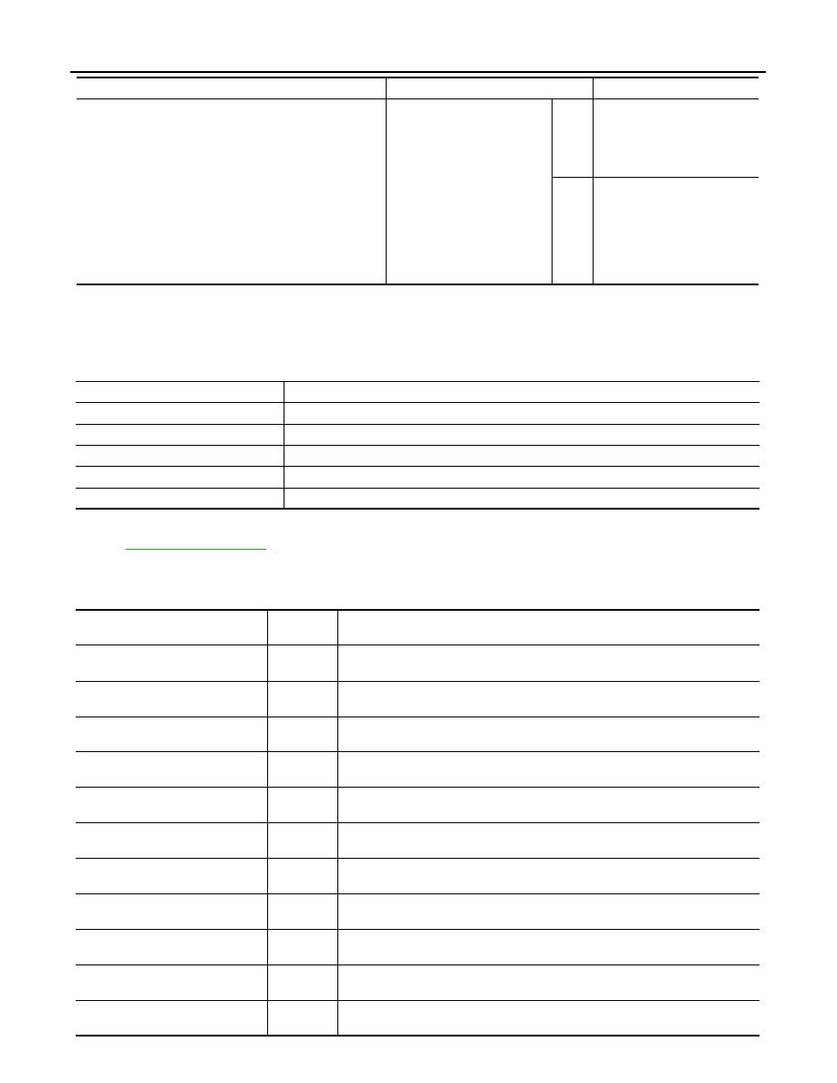
Diagnosis mode
Description
Ecu Identification
Allows confirmation of IPDM E/R part number.
Self Diagnostic Result
Displays the diagnosis results judged by IPDM E/R.
Data Monitor
Displays the real-time input/output data from IPDM E/R input/output data.
Active Test
IPDM E/R can provide a drive signal to electronic components to check their operations.
CAN Diag Support Monitor
The results of transmit/receive diagnosis of CAN communication can be read.
Monitor Item
[Unit]
MAIN SIG-
NALS
Description
RAD FAN REQ
[1/2/3/4]
×
Displays the value of the cooling fan speed request signal received from ECM via
CAN communication.
AC COMP REQ
[Off/On]
×
Displays the status of the A/C compressor request signal received from ECM via
CAN communication.
TAIL&CLR REQ
[Off/On]
×
Displays the status of the position light request signal received from BCM via CAN
communication.
HL LO REQ
[Off/On]
×
Displays the status of the low beam request signal received from BCM via CAN
communication.
HL HI REQ
[Off/On]
×
Displays the status of the high beam request signal received from BCM via CAN
communication.
FR FOG REQ
[Off/On]
×
Displays the status of the front fog light request signal received from BCM via
CAN communication.
FR WIP REQ
[Stop/1LOW/Low/Hi]
×
Displays the status of the front wiper request signal received from BCM via CAN
communication.
WIP AUTO STOP
[STOP P/ACT P]
×
Displays the status of the front wiper auto stop signal judged by IPDM E/R.
WIP PROT
[Off/BLOCK]
×
Displays the status of the front wiper fail-safe operation judged by IPDM E/R.
IGN RLY1 -REQ
[Off/On]
Displays the status of the ignition switch ON signal received from BCM via CAN
communication.
IGN RLY
[Off/On]
×
Displays the status of the ignition relay judged by IPDM E/R.