Infiniti QX56 (Z62). Manual - part 961


  Index      Infiniti     Infiniti QX56 (Z62) - service repair manual 2011 year


Search            


Content   ..  959  960  961  962   ..


Infiniti QX56 (Z62). Manual - part 961


PB-10

< SERVICE DATA AND SPECIFICATIONS (SDS) 

SERVICE DATA AND SPECIFICATIONS (SDS)

SERVICE DATA AND SPECIFICATIONS (SDS)

SERVICE DATA AND SPECIFICATIONS (SDS)

Parking Drum Brake

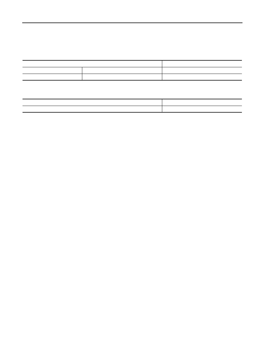
INFOID:0000000006222518

Unit: mm (in)

Parking Brake Control

INFOID:0000000006222519

Item

Limit

Brake lining

Wear thickness

1.5 (0.059)

Drum (disc of inner diameter)

Wear inner diameter

229 (9.02)

Number of notches [under force of 196 N (20 kg, 44 lb)]

6 – 7 notches

Number of notches when brake warning lamp turns ON

1 notch

PCS

PCS-1

ELECTRICAL & POWER CONTROL

C

D

E

F

G

H

I

J

K

L

B

SECTION 

PCS

A

O

P

N

CONTENTS

POWER CONTROL SYSTEM

IPDM E/R

PRECAUTION ...............................................

3

PRECAUTIONS ...................................................

3

Precaution for Supplemental Restraint System 
(SRS) "AIR BAG" and "SEAT BELT PRE-TEN-
SIONER" .................................................................
..

3

SYSTEM DESCRIPTION  ..............................

4

COMPONENT PARTS  ........................................

4

Component Parts Location ........................................

4

SYSTEM ..............................................................

5

RELAY CONTROL SYSTEM  ......................................

5

RELAY CONTROL SYSTEM : System Diagram ......

5

RELAY CONTROL SYSTEM : System Descrip-
tion ..........................................................................
..

5

RELAY CONTROL SYSTEM : Fail-Safe ...................

6

POWER CONTROL SYSTEM  .....................................

7

POWER CONTROL SYSTEM : System Diagram 

......

8

POWER CONTROL SYSTEM : System Descrip-
tion ..........................................................................
..

8

SIGNAL BUFFER SYSTEM  ........................................

8

SIGNAL BUFFER SYSTEM : System Diagram  ........

8

SIGNAL BUFFER SYSTEM : System Description 

......

8

POWER CONSUMPTION CONTROL SYSTEM  .........

8

POWER CONSUMPTION CONTROL SYSTEM : 
System Diagram ......................................................
..

9

POWER CONSUMPTION CONTROL SYSTEM : 
System Description  .................................................
..

9

DIAGNOSIS SYSTEM (IPDM E/R) .....................

10

Diagnosis Description  .............................................

10

CONSULT-III Function (IPDM E/R) .........................

12

ECU DIAGNOSIS INFORMATION ..............

15

IPDM E/R ...........................................................

15

Reference Value ......................................................

15

Fail-Safe ..................................................................

21

DTC Index ...............................................................

22

WIRING DIAGRAM  ......................................

24

IPDM E/R ...........................................................

24

Wiring Diagram ........................................................

24

DTC/CIRCUIT DIAGNOSIS  .........................

28

U1000 CAN COMM CIRCUIT  ...........................

28

Description ...............................................................

28

DTC Logic ................................................................

28

Diagnosis Procedure  ...............................................

28

B2098 IGNITION RELAY ON STUCK  ..............

29

Description ...............................................................

29

DTC Logic ................................................................

29

Diagnosis Procedure  ...............................................

29

B2099 IGNITION RELAY OFF STUCK  ............

30

Description ...............................................................

30

DTC Logic ................................................................

30

Diagnosis Procedure  ...............................................

30

POWER SUPPLY AND GROUND CIRCUIT  ....

31

Diagnosis Procedure  ...............................................

31

REMOVAL AND INSTALLATION  ...............

32

IPDM E/R ...........................................................

32

Removal and Installation  .........................................

32

POWER DISTRIBUTION SYSTEM

PRECAUTION ..............................................

33

PRECAUTIONS .................................................

33

Precaution for Supplemental Restraint System 
(SRS) "AIR BAG" and "SEAT BELT PRE-TEN-
SIONER" .................................................................

33

PCS-2

Precaution Necessary for Steering Wheel Rota-
tion after Battery Disconnect  .................................
.

33

SYSTEM DESCRIPTION  ............................

35

COMPONENT PARTS  .......................................

35

Component Parts Location  .....................................

35

Component Description .........................................

35

BCM ........................................................................

35

Ignition Relay  ..........................................................

35

Accessory Relay  .....................................................

36

Blower Relay  ..........................................................

36

Push-Button Ignition Switch ....................................

36

SYSTEM .............................................................

37

POWER DISTRIBUTION SYSTEM ...........................

37

POWER DISTRIBUTION SYSTEM : System Dia-
gram ......................................................................
.

37

POWER DISTRIBUTION SYSTEM : System De-
scription .................................................................
.

37

DIAGNOSIS SYSTEM (BCM)  ............................

39

COMMON ITEM  ........................................................

39

COMMON ITEM : CONSULT-III Function (BCM - 
COMMON ITEM)  ...................................................
.

39

INTELLIGENT KEY ...................................................

40

INTELLIGENT KEY : CONSULT-III Function 
(BCM - INTELLIGENT KEY) ..................................
.

40

ECU DIAGNOSIS INFORMATION ..............

45

BCM ...................................................................

45

List of ECU Reference  ............................................

45

WIRING DIAGRAM  .....................................

46

POWER DISTRIBUTION SYSTEM  ...................

46

Wiring Diagram  .......................................................

46

BASIC INSPECTION ...................................

53

DIAGNOSIS AND REPAIR WORK FLOW  ........

53

Work Flow ...............................................................

53

DTC/CIRCUIT DIAGNOSIS .........................

56

B2614 ACC RELAY CIRCUIT  ...........................

56

DTC Logic ...............................................................

56

Diagnosis Procedure  ..............................................

56

Component Inspection ............................................

57

B2615 BLOWER RELAY CIRCUIT  ...................

59

DTC Logic ...............................................................

59

Diagnosis Procedure  ..............................................

59

Component Inspection  ............................................

60

B2616 IGNITION RELAY CIRCUIT  ...................

61

DTC Logic  ...............................................................

61

Diagnosis Procedure ...............................................

61

Component Inspection  ............................................

62

B2618 BCM  .......................................................

63

DTC Logic  ...............................................................

63

Diagnosis Procedure ...............................................

63

B261A PUSH-BUTTON IGNITION SWITCH .....

64

DTC Logic  ...............................................................

64

Diagnosis Procedure ...............................................

64

B26F1 IGNITION RELAY  ..................................

66

DTC Logic  ...............................................................

66

Diagnosis Procedure ...............................................

66

B26F2 IGNITION RELAY  ..................................

68

DTC Logic  ...............................................................

68

Diagnosis Procedure ...............................................

68

B26F6 BCM  .......................................................

70

DTC Logic  ...............................................................

70

Diagnosis Procedure ...............................................

70

PUSH-BUTTON IGNITION SWITCH  .................

71

Component Function Check ..................................

71

Diagnosis Procedure ...............................................

71

Component Inspection  ............................................

72

PUSH-BUTTON IGNITION SWITCH POSI-
TION INDICATOR ..............................................

74

Description ..............................................................

74

Component Function Check ..................................

74

Diagnosis Procedure ...............................................

74

SYMPTOM DIAGNOSIS  ............................

76

PUSH-BUTTON IGNITION SWITCH DOES 
NOT OPERATE  .................................................

76

Description ..............................................................

76

Diagnosis Procedure ...............................................

76

PUSH-BUTTON IGNITION SWITCH POSI-
TION INDICATOR DOES NOT ILLUMINATE ...

77

Description ..............................................................

77

Diagnosis Procedure ...............................................

77

REMOVAL AND INSTALLATION ..............

78

PUSH-BUTTON IGNITION SWITCH  .................

78

Exploded View  ........................................................

78

Removal and Installation .........................................

78

PCS

PRECAUTIONS

PCS-3

< PRECAUTION >

[IPDM E/R]

C

D

E

F

G

H

I

J

K

L

B

A

O

P

N

PRECAUTION

PRECAUTIONS

Precaution for Supplemental Restraint System (SRS) "AIR BAG" and "SEAT BELT 
PRE-TENSIONER"

INFOID:0000000006220159

The Supplemental Restraint System such as “AIR BAG” and “SEAT BELT PRE-TENSIONER”, used along
with a front seat belt, helps to reduce the risk or severity of injury to the driver and front passenger for certain
types of collision. This system includes seat belt switch inputs and dual stage front air bag modules. The SRS
system uses the seat belt switches to determine the front air bag deployment, and may only deploy one front
air bag, depending on the severity of a collision and whether the front occupants are belted or unbelted.
Information necessary to service the system safely is included in the “SRS AIR BAG” and “SEAT BELT” of this
Service Manual.

WARNING:

• To avoid rendering the SRS inoperative, which could increase the risk of personal injury or death in

the event of a collision that would result in air bag inflation, all maintenance must be performed by
an authorized NISSAN/INFINITI dealer.

• Improper maintenance, including incorrect removal and installation of the SRS, can lead to personal

injury caused by unintentional activation of the system. For removal of Spiral Cable and Air Bag
Module, see the “SRS AIR BAG”.

• Do not use electrical test equipment on any circuit related to the SRS unless instructed to in this

Service Manual. SRS wiring harnesses can be identified by yellow and/or orange harnesses or har-
ness connectors.

PRECAUTIONS WHEN USING POWER TOOLS (AIR OR ELECTRIC) AND HAMMERS

WARNING:

• When working near the Air Bag Diagnosis Sensor Unit or other Air Bag System sensors with the

ignition ON or engine running, DO NOT use air or electric power tools or strike near the sensor(s)
with a hammer. Heavy vibration could activate the sensor(s) and deploy the air bag(s), possibly
causing serious injury.

• When using air or electric power tools or hammers, always switch the ignition OFF, disconnect the

battery, and wait at least 3 minutes before performing any service.


Content   ..  959  960  961  962   ..