Infiniti QX56 (Z62). Manual - part 925


  Index      Infiniti     Infiniti QX56 (Z62) - service repair manual 2011 year


Search            


Content   ..  923  924  925  926   ..


Infiniti QX56 (Z62). Manual - part 925


CHASSIS MAINTENANCE

MA-27

< PERIODIC MAINTENANCE >

C

D

E

F

G

H

I

J

K

L

M

B

MA

N

O

A

a.

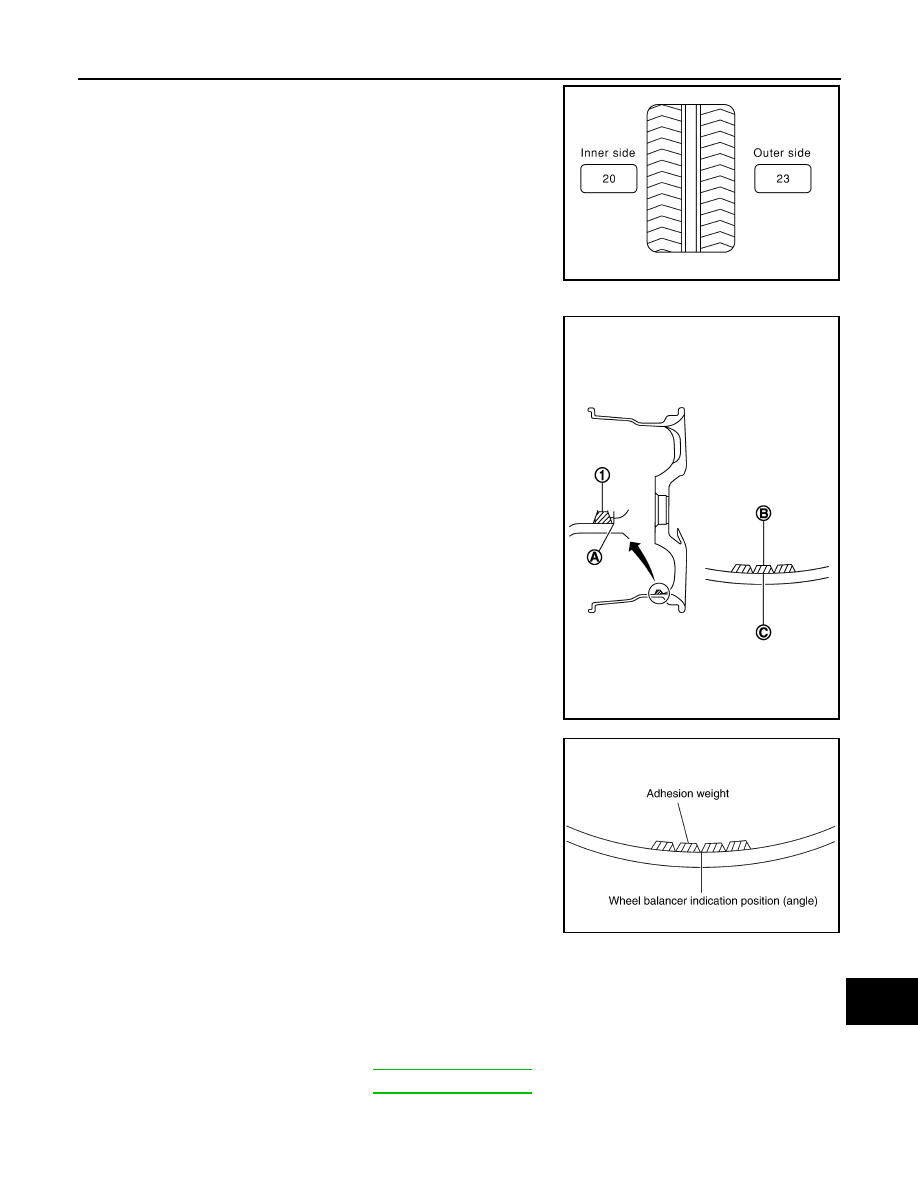
Indicated unbalance value 

×

 5/3 = balance weight to be installed

Calculation example:
23 g (0.81 oz) 

×

 5/3 = 38.33 g (1.35 oz) 

 37.5 g (1.32 oz) bal-

ance weight (closer to calculated balance weight value)
NOTE:
Note that balance weight value must be closer to the calculated
balance weight value.
Example:
36.2 

 35 g (1.23 oz)

36.3 

 37.5 g (1.32 oz)

b.

Installed balance weight in the position.
• When installing balance weight (1) to road wheels, set it into

the grooved area (A) on the inner wall of the road wheel as
shown in the figure so that the balance weight center (B) is
aligned with the tire balance machine indication position
(angle) (C).

CAUTION:

• Always use genuine NISSAN adhesion balance weights.
• Balance weights are non-reusable; always replace with

new ones.

• Never install more than four sheets of balance weight.

c.

If calculated balance weight value exceeds 50 g (1.76 oz), install
two balance weight sheets in line with each other as shown in
the figure.

CAUTION:

Never install one balance weight sheet on top of another.

3.

Start the tire balance machine again.

4.

Install drive-in balance weight on inner side of road wheel in the
tire balance machine indication position (angle).

CAUTION:

Never install more than two balance weight.

5.

Start the tire balance machine. Check that the inner and outer
residual unbalance value is within the allowable unbalance
value.

CAUTION:

If either residual unbalance value exceeds limit, repeat installation procedures.

BRAKE FLUID LEVEL AND LEAKS

SMA054D

JPEIC0040ZZ

Allowable unbalance value

Dynamic (At flange)

: Refer to 

WT-69, "Road Wheel"

.

Static (At flange)

: Refer to 

WT-69, "Road Wheel"

.

PEIA0033E

MA-28

< PERIODIC MAINTENANCE >

CHASSIS MAINTENANCE

BRAKE FLUID LEVEL AND LEAKS : Inspection

INFOID:0000000006220939

• Check that the fluid level in the sub tank is within the specified range (MAX – MIN lines).

CAUTION:

Turn OFF the ignition switch and depress the brake pedal 20 times or more to check brake fluid level.
NOTE:
Since brake fluid is in the accumulator in pressurized condition, the reservoir tank brake fluid level should be
lower than the MAX line.

• Visually check for any brake fluid leakage around the reservoir tank.
• Check the brake system for any leakage if the fluid level is extremely low (lower than MIN).
• Check the brake system for fluid leakage if the warning lamp remains illuminated even after the parking

brake is released.

• Check the sub tank for the mixing of foreign matter (e.g. dust) and oils other than brake fluid.

BRAKE LINES AND CABLES

BRAKE LINES AND CABLES : Inspection

INFOID:0000000006220940

1.

Check brake line (tubes and hoses) for cracks, deterioration or other damage. Replace any damaged
parts.

2.

Depress the brake pedal with a force of 490 N (50 kg, 110lb) and
hold down the pedal for approx. 5 seconds with the engine run-
ning. Check for any fluid leakage.

CAUTION:

Retighten the applicable connection to the specified torque
and repair any abnormal (damaged, worn or deformed) part
if any brake fluid leakage is present).

BRAKE FLUID

BRAKE FLUID : Bleeding Brake System

INFOID:0000000006220941

CAUTION:

• Bleed air in the following order: motor/accumulator assembly 

 front right brake 

 front left brake

 rear left brake 

 and rear right brake.

• The VDC warning lamp, ABS warning lamp and brake warning lamp turn ON and DTC “C118E” may

be detected in self-diagnosis result for “ABS” with CONSULT-III when the brake pedal is excessively
operated, such as air bleeding. This is not a system malfunction because this occurs due to the tem-
porary decrease in accumulator fluid pressure. The system returns to normal condition when the
accumulator fluid pressure reaches the specified pressure with the ignition switch ON and the VDC
warning lamp, ABS warning lamp, and brake warning lamp turn OFF. After these steps, erase self-
diagnosis results for “ABS” with CONSULT-III. 

- DTC other than “C118E” is detected: Refer to 

BRC-51, "DTC Index"

.

NOTE:
When the ignition switch is ON, the brake warning lamp may turns ON even when the parking brake pedal is
released with the brake fluid within the specified level. This indicates the decrease in accumulator fluid pres-
sure.

MOTOR/ACCUMULATOR ASSEMBLY

CAUTION:

• If the brake fluid adheres to the brake caliper assembly and disc rotor, quickly wipe it off.
• Never spill or splash brake fluid on painted surfaces. Brake fluid may seriously damage paint. Wipe it

off immediately and wash with water if it gets on a painted surface.

• Never operate the brake pedal with the reservoir cap removed. Failure to do this may cause the scat-

tering of brake fluid.

•  Never operate the brake pedal excessively during the work procedure.
• Monitor the fluid level in the reservoir tank while performing the air bleeding.

SBR389C

CHASSIS MAINTENANCE

MA-29

< PERIODIC MAINTENANCE >

C

D

E

F

G

H

I

J

K

L

M

B

MA

N

O

A

• Bleed air in the following order: motor/accumulator assembly 

 front right brake 

 front left brake

 rear left brake 

 and rear right brake.

1.

Turn the ignition switch OFF.

2.

Depress the brake pedal 20 times or more.

3.

Check that there is no foreign material in the reservoir tank, and refill with new brake fluid.

CAUTION:

• Never reuse drained brake fluid.
• Never allow oils other than brake fluid to enter the reservoir tank.

4.

Turn the ignition switch ON.
NOTE:
The motor is activated and automatically stops.

5.

Turn the ignition switch OFF.

6.

Depress the brake pedal 20 times or more.
NOTE:
The pressure loss in the accumulator results in a large brake pedal stroke. In addition to this, the brake
pedal depression becomes lighter in initial stage.

7.

Repeat steps 4 to 6 for 5 times.

8.

Turn the ignition switch ON to check that the time between motor activation and automatic stop is less
than 18 seconds. If the time is 18 seconds or more, repeat from Step 4 to 8.

FRONT BRAKE

CAUTION:

• If the brake fluid adheres to the brake caliper assembly and disc rotor, quickly wipe it off.
• Never spill or splash brake fluid on painted surfaces. Brake fluid may seriously damage paint. Wipe it

off immediately and wash with water if it gets on a painted surface.

• Never operate the brake pedal with the reservoir cap removed. Failure to do this may cause the scat-

tering of brake fluid.

• Never operate the brake pedal excessively during the work procedure.
• Monitor the fluid level in the reservoir tank while performing the air bleeding.
• Bleed air in the following order: motor/accumulator assembly 

 front right brake 

 front left brake

 rear left brake 

 and rear right brake.

1.

Turn the ignition switch OFF.

2.

Depress the brake pedal 20 times or more.
NOTE:
The pressure loss in the accumulator results in a large brake pedal stroke. In addition to this, the brake
pedal depression becomes lighter in initial stage.

3.

Check that there is no foreign material in the reservoir tank, and refill with new brake fluid.

CAUTION:

• Never reuse drained brake fluid.
• Never allow oils other than brake fluid to enter the reservoir tank.

4.

Turn the ignition switch ON.

5.

Connect a vinyl tube to the bleed valve.

6.

Depress the brake pedal and loosen the bleeder valve.

7.

Repeat steps 1 to 6 until all of the air is out of the brake line and tighten the air bleeder to the specified
torque with the brake pedal depressed. Refer to 

BR-36, "BRAKE CALIPER ASSEMBLY : Exploded View"

.

8.

Check that no drag feel is present for the front disc brake. Refer to 

BR-39, "BRAKE CALIPER ASSEMBLY

: Inspection"

.

9.

Check each item of brake pedal. Adjust it if the measurement value is not the standard. Refer to 

BR-7,

"Inspection and Adjustment"

.

REAR BRAKE

CAUTION:

• If the brake fluid adheres to the brake caliper assembly and disc rotor, quickly wipe it off.
• Never spill or splash brake fluid on painted surfaces. Brake fluid may seriously damage paint. Wipe it

off immediately and wash with water if it gets on a painted surface.

• Never operate the brake pedal with the reservoir cap removed. Failure to do this may cause the scat-

tering of brake fluid.

MA-30

< PERIODIC MAINTENANCE >

CHASSIS MAINTENANCE

• Never operate the brake pedal excessively during the work procedure.
• Monitor the fluid level in the reservoir tank while performing the air bleeding.
• Bleed air in the following order: motor/accumulator assembly 

 front right brake 

 front left brake

 rear left brake 

 and rear right brake.

1.

Turn the ignition switch OFF.

2.

Depress the brake pedal 20 times or more.
NOTE:
The pressure loss in the accumulator results in a large brake pedal stroke. In addition to this, the brake
pedal depression becomes lighter in initial stage.

3.

Check that there is no foreign material in the reservoir tank, and refill with new brake fluid.

CAUTION:

• Never reuse drained brake fluid.
• Never allow oils other than brake fluid to enter the reservoir tank.

4.

Turn the ignition switch ON.

5.

Connect a vinyl tube to the bleed valve.

6.

Depress the brake pedal and loosen the bleeder valve.

7.

Depress and hold the brake pedal depression to discharge 100 cc of brake fluid before tightening the air
bleeder to the specified torque. Refer to 

BR-42, "BRAKE CALIPER ASSEMBLY : Exploded View"

.

NOTE:
Since brake fluid is conveyed by the motor, the brake pedal is not necessarily depressed.

8.

Release the brake pedal.

9.

Repeat steps 1 to 8 until all of the air is out of the brake line and tighten the air bleeder to the specified
torque with the brake pedal depressed. Refer to 

BR-42, "BRAKE CALIPER ASSEMBLY : Exploded View"

.

10. Check that no drag feel is present for the rear disc brake. Refer to 

BR-45, "BRAKE CALIPER ASSEMBLY

: Inspection"

.

11. Check each item of brake pedal. Adjust it if the measurement value is not the standard. Refer to 

BR-7,

"Inspection and Adjustment"

.

BRAKE FLUID LEVEL ADJUSTMENT AFTER AIR BLEEDING

1.

Turn the ignition switch OFF.

2.

Depress the brake pedal 20 times or more.
NOTE:
The pressure loss in the accumulator results in a large brake pedal stroke. In addition to this, the brake
pedal depression becomes lighter in initial stage.

3.

Adjust brake fluid level to the reservoir tank MAX line.

CAUTION:

Never adjust with the ignition switch ON.

4.

Turn the ignition switch ON.

5.

Check that the reservoir tank brake fluid level is 4 

 12 mm (0.16

 0.47 in) lower than the MAX line.

NOTE:
Since brake fluid is in the accumulator in pressurized condition,
the reservoir tank brake fluid level should be lower than the MAX
line.

DISC BRAKE

DISC BRAKE : Inspection

INFOID:0000000006220942

DISC ROTOR

Check condition, wear, and damage.

CALIPER

• Check for leakage.

JPFIA0769ZZ


Content   ..  923  924  925  926   ..