Infiniti QX56 (Z62). Manual - part 898


  Index      Infiniti     Infiniti QX56 (Z62) - service repair manual 2011 year


Search            


Content   ..  896  897  898  899   ..


Infiniti QX56 (Z62). Manual - part 898


LAN

CAN COMMUNICATION CIRCUIT 1

LAN-169

< DTC/CIRCUIT DIAGNOSIS >

[CAN SYSTEM (TYPE 2)]

C

D

E

F

G

H

I

J

K

L

B

A

O

P

N

CAN COMMUNICATION CIRCUIT 1

Diagnosis Procedure

INFOID:0000000006256313

1.

CONNECTOR INSPECTION

1.

Turn the ignition switch OFF.

2.

Disconnect the battery cable from the negative terminal.

3.

Disconnect all the unit connectors on CAN communication circuit 1.
NOTE:
For identification of CAN communication circuit 1, CAN communication circuit 2, and ITS communication
circuit, refer to 

LAN-57, "System Diagram"

.

4.

Check terminals and connectors for damage, bend and loose connection.

Is the inspection result normal?

YES

>> GO TO 2.

NO

>> Repair the terminal and connector.

2.

CHECK HARNESS CONTINUITY (SHORT CIRCUIT)

Check the continuity between the data link connector terminals.

Is the inspection result normal?

YES

>> GO TO 3.

NO

>> Check the harness and repair the root cause.

3.

CHECK HARNESS CONTINUITY (SHORT CIRCUIT)

Check the continuity between the data link connector and the ground.

Is the inspection result normal?

YES

>> GO TO 4.

NO

>> Check the harness and repair the root cause.

4.

CHECK ECM AND IPDM E/R TERMINATION CIRCUIT

1.

Remove the ECM and the IPDM E/R.

2.

Check the resistance between the ECM terminals.

3.

Check the resistance between the IPDM E/R terminals.

Is the measurement value within the specification?

YES

>> GO TO 5.

NO

>> Replace the ECM and/or the IPDM E/R.
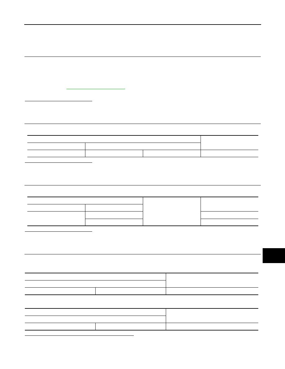
Data link connector

Continuity

Connector No.

Terminal No.

M4

6

14

Not existed

Data link connector

Ground

Continuity

Connector No.

Terminal No.

M4

6

Not existed

14

Not existed

ECM

Resistance (

)

Terminal No.

146

151

Approx. 108 – 132

IPDM E/R

Resistance (

)

Terminal No.

27

26

Approx. 108 – 132

LAN-170

< DTC/CIRCUIT DIAGNOSIS >

[CAN SYSTEM (TYPE 2)]

CAN COMMUNICATION CIRCUIT 1

5.

CHECK SYMPTOM

Connect all the connectors. Check if the symptoms described in the “Symptom (Results from interview with
customer)” are reproduced. 

Inspection result

Reproduced>>GO TO 6.
Non-reproduced>>Start the diagnosis again. Follow the trouble diagnosis procedure when past error is

detected.

6.

CHECK UNIT REPRODUCTION

Perform the reproduction test as per the following procedure for each unit.
1.

Turn the ignition switch OFF.

2.

Disconnect the battery cable from the negative terminal.

3.

Disconnect one of the unit connectors of CAN communication circuit 1.
NOTE:
ECM and IPDM E/R have a termination circuit. Check other units first.

4.

Connect the battery cable to the negative terminal. Check if the symptoms described in the “Symptom
(Results from interview with customer)” are reproduced. 
NOTE:
Although unit-related error symptoms occur, do not confuse them with other symptoms. 

Inspection result

Reproduced>>Connect the connector. Check other units as per the above procedure.
Non-reproduced>>Replace the unit whose connector was disconnected.

LAN

CAN COMMUNICATION CIRCUIT 2

LAN-171

< DTC/CIRCUIT DIAGNOSIS >

[CAN SYSTEM (TYPE 2)]

C

D

E

F

G

H

I

J

K

L

B

A

O

P

N

CAN COMMUNICATION CIRCUIT 2

Diagnosis Procedure

INFOID:0000000006256314

1.

CONNECTOR INSPECTION

1.

Turn the ignition switch OFF.

2.

Disconnect the battery cable from the negative terminal.

3.

Disconnect all the unit connectors on CAN communication circuit 2.
NOTE:
For identification of CAN communication circuit 1, CAN communication circuit 2, and ITS communication
circuit, refer to 

LAN-57, "System Diagram"

.

4.

Check terminals and connectors for damage, bend and loose connection.

Is the inspection result normal?

YES

>> GO TO 2.

NO

>> Repair the terminal and connector.

2.

CHECK HARNESS CONTINUITY (SHORT CIRCUIT)

Check the continuity between the data link connector terminals.

Is the inspection result normal?

YES

>> GO TO 3.

NO

>> Check the harness and repair the root cause.

3.

CHECK HARNESS CONTINUITY (SHORT CIRCUIT)

Check the continuity between the data link connector and the ground.

Is the inspection result normal?

YES

>> GO TO 4.

NO

>> Check the harness and repair the root cause.

4.

CHECK CAN GATEWAY TERMINATION CIRCUIT

1.

Remove the CAN gateway.

2.

Check the resistance between the CAN gateway terminals.

Is the measurement value within the specification?

YES

>> GO TO 5.

NO

>> Replace the CAN gateway.

5.

CHECK SYMPTOM

Connect all the connectors. Check if the symptoms described in the “Symptom (Results from interview with
customer)” are reproduced. 

Inspection result

Reproduced>>GO TO 6.

Data link connector

Continuity

Connector No.

Terminal No.

M4

13

12

Not existed

Data link connector

Ground

Continuity

Connector No.

Terminal No.

M4

13

Not existed

12

Not existed

CAN gateway

Resistance (

)

Terminal No.

4

10

Approx. 108 – 132

6

12

Approx. 108 – 132

LAN-172

< DTC/CIRCUIT DIAGNOSIS >

[CAN SYSTEM (TYPE 2)]

CAN COMMUNICATION CIRCUIT 2

Non-reproduced>>Start the diagnosis again. Follow the trouble diagnosis procedure when past error is

detected.

6.

CHECK UNIT REPRODUCTION

Perform the reproduction test as per the following procedure for each unit.
1.

Turn the ignition switch OFF.

2.

Disconnect the battery cable from the negative terminal.

3.

Disconnect one of the unit connectors of CAN communication circuit 2.
NOTE:
CAN gateway has two termination circuits. Check other units first.

4.

Connect the battery cable to the negative terminal. Check if the symptoms described in the “Symptom
(Results from interview with customer)” are reproduced. 
NOTE:
Although unit-related error symptoms occur, do not confuse them with other symptoms. 

Inspection result

Reproduced>>Connect the connector. Check other units as per the above procedure.
Non-reproduced>>Replace the unit whose connector was disconnected.


Content   ..  896  897  898  899   ..