Infiniti QX56 (Z62). Manual - part 862


  Index      Infiniti     Infiniti QX56 (Z62) - service repair manual 2011 year


Search            


Content   ..  860  861  862  863   ..


Infiniti QX56 (Z62). Manual - part 862


LAN

PRECAUTIONS

LAN-25

< PRECAUTION >

[CAN]

C

D

E

F

G

H

I

J

K

L

B

A

O

P

N

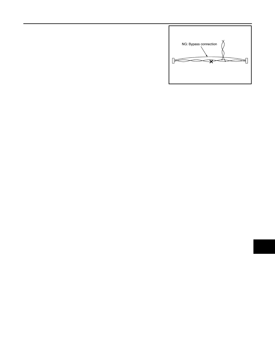
• Bypass connection is never allowed at the repaired area.

NOTE:
Bypass connection may cause CAN communication error. The
spliced wire becomes separated and the characteristics of twisted
line are lost. 

• Replace the applicable harness as an assembly if error is detected on the shield lines of CAN communica-

tion line.

SKIB8767E

LAN-26

< SYSTEM DESCRIPTION >

[CAN]

COMPONENT PARTS

SYSTEM DESCRIPTION

COMPONENT PARTS

Component Parts Location

INFOID:0000000006220530

1.

Air bag diagnosis sensor unit

2.

Lane camera unit

3.

A/T assembly

4.

AFS control unit

5.

Transfer control unit

6.

Low tire pressure warning control 
unit

7.

IPDM E/R

8.

CAN gateway

9.

ECM

10. A/C auto amp.

11.

ICC sensor

12. AV control unit

13. BCM

14. ABS actuator and electric unit (con-

trol unit)

15. Combination meter

16. Data link connector

17. Steering angle sensor

18. Accelerator pedal actuator

19. Driver seat control unit

20. Pre-crash seat belt control unit (driv-

er side)

21. Air levelizer control module

22. ADAS control unit

23. Automatic back door control module 24. Side radar LH

25. Side radar RH

JSMIA0343ZZ

LAN

SYSTEM

LAN-27

< SYSTEM DESCRIPTION >

[CAN]

C

D

E

F

G

H

I

J

K

L

B

A

O

P

N

SYSTEM

CAN COMMUNICATION SYSTEM

CAN COMMUNICATION SYSTEM : CAN System Specification Chart

INFOID:0000000006220532

Determine CAN system type from the following specification chart.
NOTE:
Refer to 

LAN-18, "Trouble Diagnosis Procedure"

 for how to use CAN system specification chart.

×

: Applicable

VEHICLE EQUIPMENT IDENTIFICATION INFORMATION

NOTE:

Body type

Wagon

Axle

2WD

4WD

Engine

VK56VD

Transmission

A/T

Brake control

VDC

ICC system

×

×

CAN system type

1

2

3

4

CAN communication unit

ECM

×

×

×

×

Transfer control unit

×

×

ABS actuator and electric unit (control unit)

×

×

×

×

TCM

×

×

×

×

Air bag diagnosis sensor unit

×

×

×

×

AFS control unit

×

×

AV control unit

×

×

×

×

BCM

×

×

×

×

CAN gateway

×

×

Data link connector

×

×

×

×

A/C auto amp.

×

×

×

×

Combination meter

×

×

×

×

Steering angle sensor

×

×

×

×

Low tire pressure warning control unit

×

×

×

×

IPDM E/R

×

×

×

×

Driver seat control unit

×

×

×

×

Pre-crash seat belt control unit (driver side)

×

×

Air levelizer control module

×

×

×

×

ADAS control unit

×

×

Automatic back door control module

×

×

×

×

ITS communication unit

ADAS control unit

×

×

Side radar RH

×

×

Side radar LH

×

×

Lane camera unit

×

×

Accelerator pedal actuator

×

×

ICC sensor

×

×

LAN-28

< SYSTEM DESCRIPTION >

[CAN]

SYSTEM

Check CAN system type from the vehicle shape and equipment.

CAN COMMUNICATION SYSTEM : CAN Communication Signal Chart

INFOID:0000000006220533

Refer to 

LAN-17, "How to Use CAN Communication Signal Chart"

 for how to use CAN communication signal

chart.

T: Transmit

R: Receive

1.

ICC sensor

A.

With ICC system

JSMIA0342ZZ

Signal name

ECM

4W

D

ABS

TCM

A-BA

G

AFS

AV

BCM

CGW

HV

AC

M&

A

STRG

TPMS

IPDM

-E

ADP

PSB

E-SUS

IC

C

PWB

D

A/C compressor request 
signal

T

R

Accelerator pedal position 
signal

T

R

R

R

R

ASCD OD cancel request 
signal

T

R

ASCD operation signal

T

R

ASCD status signal

T

R

Closed throttle position sig-
nal

T

R

Cooling fan speed request 
signal

T

R

Engine and A/T integrated 
control signal

T

R

R

T

Engine coolant temperature 
signal

T

R

R

Engine restart request sig-
nal

T

R

R

T

R

Engine speed signal

T

R

R

R

R

R

R

R

Engine status signal

T

R

R

R

Engine torque signal

T

R

Fuel consumption monitor 
signal

T

R

R

ICC brake switch signal

T

R

ICC prohibition signal

T

R

ICC steering switch signal

T

R

Malfunctioning indicator 
lamp signal

T

R

N idle instruction signal

T

R

R

T


Content   ..  860  861  862  863   ..