Infiniti QX56 (Z62). Manual - part 859


  Index      Infiniti     Infiniti QX56 (Z62) - service repair manual 2011 year


Search            


Content   ..  857  858  859  860   ..


Infiniti QX56 (Z62). Manual - part 859


LAN

TROUBLE DIAGNOSIS

LAN-13

< SYSTEM DESCRIPTION >

[CAN FUNDAMENTAL]

C

D

E

F

G

H

I

J

K

L

B

A

O

P

N

NOTE:
• When data link connector branch line is open, transmission and reception of CAN communication signals

are not affected. Therefore, no symptoms occur. However, be sure to repair malfunctioning circuit.

• The model (all units on CAN communication system are Diag on CAN) cannot perform CAN diagnosis with

CONSULT-III if the following error occurs. The error is judged by the symptom.

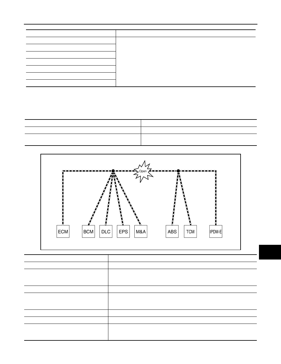
Example: Main Line Between Data Link Connector and ABS Actuator and Electric Unit (Control Unit) Open Circuit

Unit name

Major symptom

ECM

Normal operation.

BCM

EPS control unit

Combination meter

ABS actuator and electric unit (control unit)

TCM

IPDM E/R

Error

Difference of symptom

Data link connector branch line open circuit

Normal operation.

CAN-H, CAN-L harness short-circuit

Most of the units which are connected to the CAN communication 
system enter fail-safe mode or are deactivated.

SKIB8740E

Unit name

Major symptom

ECM

Engine torque limiting is affected, and shift harshness increases.

BCM

• Reverse warning chime does not sound.
• The front wiper moves under continuous operation mode even though the front wip-

er switch being in the intermittent position.

EPS control unit

The steering effort increases.

Combination meter

• The shift position indicator and OD OFF indicator turn OFF.
• The speedometer is inoperative.
• The odo/trip meter stops.

ABS actuator and electric unit (control unit)

Normal operation.

TCM

No impact on operation.

IPDM E/R

When the ignition switch is ON,
• The headlamps (Lo) turn ON.
• The cooling fan continues to rotate.

LAN-14

< SYSTEM DESCRIPTION >

[CAN FUNDAMENTAL]

TROUBLE DIAGNOSIS

Example: CAN-H, CAN-L Harness Short Circuit

CAN Diagnosis with CONSULT-III

INFOID:0000000006220519

CAN diagnosis on CONSULT-III extracts the root cause by receiving the following information.
• Response to the system call
• Control unit diagnosis information
• Self-diagnosis
• CAN diagnostic support monitor

SKIB8741E

Unit name

Major symptom

ECM

• Engine torque limiting is affected, and shift harshness increases.
• Engine speed drops.

BCM

• Reverse warning chime does not sound.
• The front wiper moves under continuous operation mode even though the front 

wiper switch being in the intermittent position.

• The room lamp does not turn ON.
• The engine does not start (if an error or malfunction occurs while turning the igni-

tion switch OFF.)

• The steering lock does not release (if an error or malfunction occurs while turning 

the ignition switch OFF.)

EPS control unit

The steering effort increases.

Combination meter

• The tachometer and the speedometer do not move.
• Warning lamps turn ON.
• Indicator lamps do not turn ON.

ABS actuator and electric unit (control unit)

Normal operation.

TCM

No impact on operation.

IPDM E/R

When the ignition switch is ON,
• The headlamps (Lo) turn ON.
• The cooling fan continues to rotate.

LAN

TROUBLE DIAGNOSIS

LAN-15

< SYSTEM DESCRIPTION >

[CAN FUNDAMENTAL]

C

D

E

F

G

H

I

J

K

L

B

A

O

P

N

Self-Diagnosis

INFOID:0000000006220520

CAN Diagnostic Support Monitor

INFOID:0000000006220521

MONITOR ITEM (CONSULT-III)

Example: CAN DIAG SUPPORT MNTR indication

Without PAST

DTC

Self-diagnosis item

 (CONSULT-III indication)

DTC detection condition

Inspection/Action

U0101

LOST COMM (TCM)

When ECM is not transmitting or receiving CAN communi-
cation signal of OBD (emission-related diagnosis) from 
TCM for 2 seconds or more.

Start the inspection. Re-
fer to the applicable sec-
tion of the indicated 
control unit.

U0140

LOST COMM (BCM)

When ECM is not transmitting or receiving CAN communi-
cation signal of OBD (emission-related diagnosis) from 
BCM for 2 seconds or more.

U0164

LOST COMM (HVAC)

When ECM is not transmitting or receiving CAN communi-
cation signal of OBD (emission-related diagnosis) from A/
C auto amp. or unified meter and A/C amp. for 2 seconds 
or more.

U1000

CAN COMM CIRCUIT

ECM

When ECM is not transmitting or receiving CAN 
communication signal of OBD (emission-relat-
ed diagnosis) for 2 seconds or more.

Except 
for ECM

When a control unit (except for ECM) is not 
transmitting or receiving CAN communication 
signal for 2 seconds or more.

U1001

CAN COMM CIRCUIT

When ECM is not transmitting or receiving CAN communi-
cation signal other than OBD (emission-related diagnosis) 
for 2 seconds or more.

U1002

SYSTEM COMM

When a control unit is not transmitting or receiving CAN 
communication signal for 2 seconds or less.

U1010

CONTROL UNIT(CAN)

When an error is detected during the initial diagnosis for 
CAN controller of each control unit.

Replace the control unit 
indicating “U1010” or 
“P0607”.

P0607

ECM

U1507

LOST COMM (SIDE RDR R)

When ADAS control unit is not receiving CAN communica-
tion signal from side radar RH for 2 seconds or more.

Start the inspection. Re-
fer to the applicable sec-
tion of the indicated 
control unit.

U1508

LOST COMM (SIDE RDR L)

When ADAS control unit is not receiving CAN communica-
tion signal from side radar LH for 2 seconds or more.

JSMIA0015GB

LAN-16

< SYSTEM DESCRIPTION >

[CAN FUNDAMENTAL]

TROUBLE DIAGNOSIS

With PAST

MONITOR ITEM (ON-BOARD DIAGNOSIS)

NOTE:
For some models, CAN communication diagnosis result is received from the vehicle monitor.

Example: Vehicle Display 

Item

PRSNT

Description

Initial diagnosis

OK

Normal at present

NG

Control unit error (Except for some control units)

Transmission diagnosis

OK

Normal at present

UNKWN

Unable to transmit signals for 2 seconds or more.

Diagnosis not performed

Control unit name

(Reception diagnosis)

OK

Normal at present

UNKWN

Unable to receive signals for 2 seconds or more.

Diagnosis not performed

No control unit for receiving signals. (No applicable optional parts)

Item

PRSNT

PAST

Description

Transmission diagnosis

OK

OK

Normal at present and in the past

1 – 39

Normal at present, but unable to transmit signals for 2 seconds or more 
in the past. (The number indicates the number of ignition switch cycles 
from OFF to ON.)

UNKWN

0

Unable to transmit signals for 2 seconds or more at present.

Control unit name

(Reception diagnosis)

OK

OK

Normal at present and in the past

1 – 39

Normal at present, but unable to receive signals for 2 seconds or more 
in the past. (The number indicates the number of ignition switch cycles 
from OFF to ON.)

UNKWN

0

Unable to receive signals for 2 seconds or more at present.

Diagnosis not performed.

No control unit for receiving signals. (No applicable optional parts)

Item

Result indi-

cated

Error counter

Description

CAN_COMM

(Initial diagnosis)

OK

0

Normal at present

NG

1 – 50

Control unit error
(The number indicates how many times diagnosis has been 
run.)

CAN_CIRC_1

(Transmission diagnosis)

OK

0

Normal at present

UNKWN

1 – 50

Unable to transmit for 2 seconds or more at present.
(The number indicates how many times diagnosis has been 
run.)

CAN_CIRC_2 – 9

(Reception diagnosis of each unit)

OK

0

Normal at present

UNKWN

1 – 50

Unable to transmit for 2 seconds or more at present.
(The number indicates how many times diagnosis has been 
run.)

Diagnosis not performed.

No control unit for receiving signals. (No applicable optional 
parts)


Content   ..  857  858  859  860   ..