Infiniti QX56 (Z62). Manual - part 768


  Index      Infiniti     Infiniti QX56 (Z62) - service repair manual 2011 year


Search            


Content   ..  766  767  768  769   ..


Infiniti QX56 (Z62). Manual - part 768


COMPONENT PARTS

HA-13

< SYSTEM DESCRIPTION >

C

D

E

F

G

H

J

K

L

M

A

B

HA

N

O

P

SYSTEM DESCRIPTION

COMPONENT PARTS

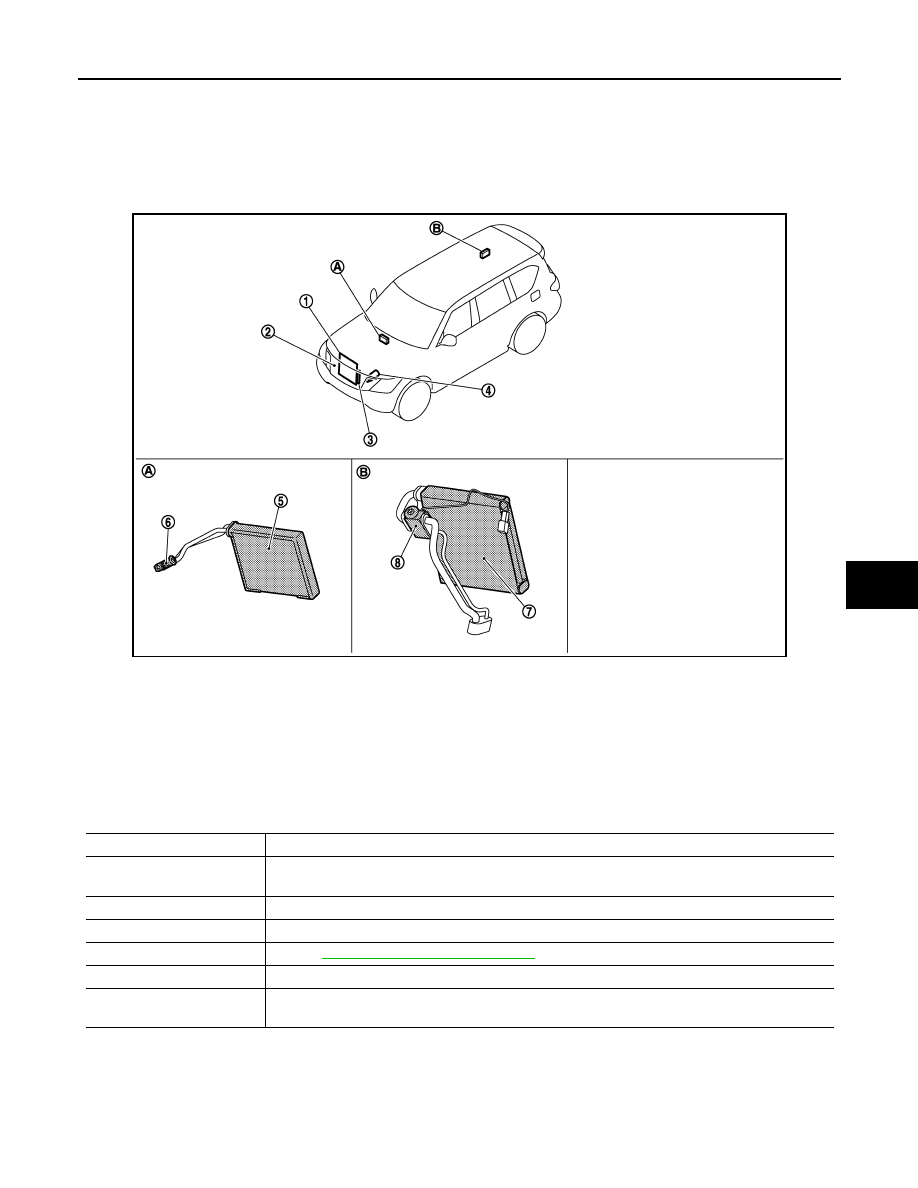
Component Parts Location

INFOID:0000000006276144

Component Description

INFOID:0000000006276145

JMIIA0920ZZ

1.

Condenser

2.

Refrigerant pressure sensor

3.

Liquid tank

4.

Compressor

5.

Front evaporator

6.

Front expansion valve

7.

Rear evaporator

8.

Rear expansion valve

A.

Built-in heater & cooling unit assem-
bly

B.

Built-in rear coolier unit assembly

Component

Description

Evaporator

The mist form liquid refrigerant transforms to gas by evaporation by the air conveyed from blower 
motor. The air is cooled by the heat by evaporation.

Condenser

Cools refrigerant discharged from compressor, and transforms it to liquid refrigerant.

Compressor

Intakes, compresses, and discharges refrigerant, to circulate refrigerant inside the refrigerant cycle.

Refrigerant pressure sensor

Refer to 

EC-32, "Refrigerant Pressure Sensor"

 .

Liquid tank

Eliminates foreign matter in refrigerant, and stores temporarily liquid refrigerant.

Expansion valve

Transforms high-pressure liquid refrigerant to mist form low-pressure liquid refrigerant by drawing 
function.

HA-14

< SYSTEM DESCRIPTION >

SYSTEM

SYSTEM

System Diagram

INFOID:0000000006276146

System Description

INFOID:0000000006276147

REFRIGERANT CYCLE

Refrigerant Flow

JMIIA0921GB

SYSTEM

HA-15

< SYSTEM DESCRIPTION >

C

D

E

F

G

H

J

K

L

M

A

B

HA

N

O

P

The refrigerant from the compressor, frows the condenser with liquid tank, the evaporator, and returns to the
compressor. The refrigerant evaporation in the evaporator is controlled by an expansion valve.

Freeze Protection

Automatic air conditioner

• When intake sensor detects that evaporator surface temperature is 2.5

°

C (37

°

F) or less, A/C auto amp.

requests BCM to turn the compressor OFF.

• BCM requests ECM to turn the compressor to OFF by the signal from A/C auto amp., and ECM makes A/C

relay to OFF, and stops the compressor.

REFRIGERANT SYSTEM PROTECTION

Refrigerant Pressure Sensor

• The refrigerant system is protected against excessively high- or low-pressures by the refrigerant pressure

sensor, installed at the condenser exit. The refrigerant pressure sensor detects the pressure inside the
refrigerant line and sends the voltage signal to the ECM if the system pressure rises above, or falls below
the specifications. 

• ECM turns the A/C relay to OFF and stops the compressor when the high-pressure side detected by refriger-

ant pressure sensor is following conditions;

- Approximately 3,120 kPa (31.8 kg/cm

2

, 452 psi) or more (Engine speed is less than 1,500 rpm.)

- Approximately 2,740 kPa (27.9 kg/cm

2

, 397 psi) or more (Engine speed is 1,500 rpm or more.)

- Approximately 140 kPa (1.4 kg/cm

2

, 20 psi) or less

Pressure Relief Valve

The refrigerant system is also protected by a pressure relief valve, located in the rear head of the compressor.
The release port on the pressure relief valve automatically opens and releases refrigerant into the atmosphere
when the pressure of refrigerant in the system increases to an unusual level [more than 3,800 kPa (38.8 kg/
cm

2

, 551 psi)].

HA-16

< BASIC INSPECTION >

DIAGNOSIS AND REPAIR WORKFLOW

BASIC INSPECTION

DIAGNOSIS AND REPAIR WORKFLOW

Work Flow

INFOID:0000000006276148

OVERALL SEQUENCE

DETAILED FLOW

1.

INTERVIEW FOR MALFUNCTION

Interview the symptom to the customer.

NNIIA0143GB


Content   ..  766  767  768  769   ..