Infiniti QX56 (Z62). Manual - part 729
FAX-18
< REMOVAL AND INSTALLATION >
[4WD]
FRONT WHEEL HUB AND KNUCKLE
REMOVAL AND INSTALLATION
FRONT WHEEL HUB AND KNUCKLE
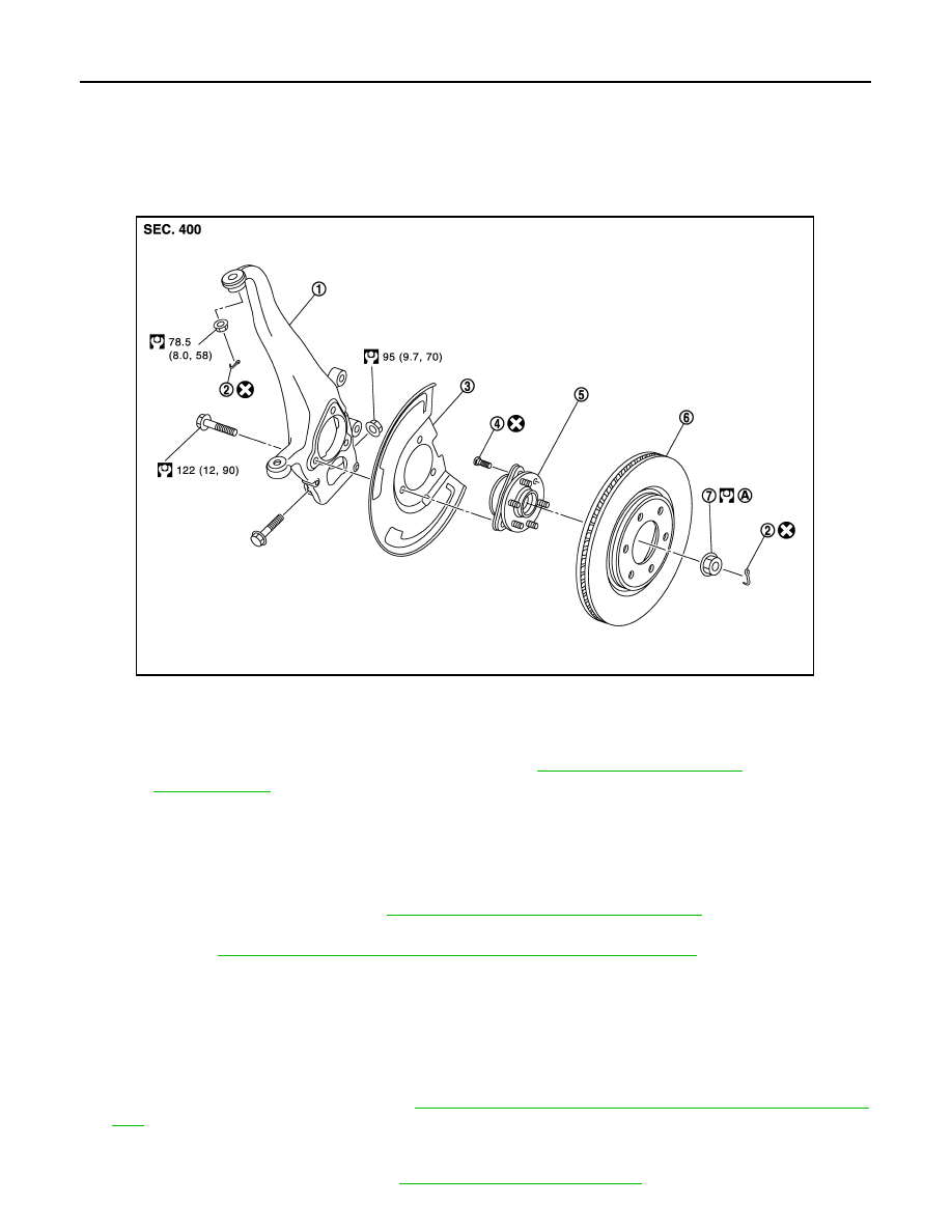
Exploded View
INFOID:0000000006225396
Removal and Installation
INFOID:0000000006225397
REMOVAL
1.
Remove tires.
2.
Remove brake hose bracket. Refer to
BR-23, "FRONT : Removal and Installation"
3.
Remove caliper assembly mounting bolts. Hang caliper assembly in a place where it will not interfere with
work. Refer to
BR-37, "BRAKE CALIPER ASSEMBLY : Removal and Installation"
CAUTION:
Never depress brake pedal while brake caliper is removed.
4.
Remove disc rotor.
CAUTION:
• Put matching marks on the wheel hub and bearing assembly and the disc rotor before removing
the disc rotor.
• Never drop disc rotor.
5.
Remove wheel sensor harness. Refer to
BRC-134, "FRONT WHEEL SENSOR : Removal and Installa-
CAUTION:
Never pull on wheel sensor harness.
6.
Remove steering outer socket. Refer to
ST-42, "Removal and Installation"
1.
Steering knuckle
2.
Cotter pin
3.
Splash guard
4.
Hub bolt
5.
Wheel hub and bearing assembly
6.
Disc rotor
7.
Wheel hub lock nut
A.
Tightening must be done following the installation procedure. Refer to
FAX-18, "Removal and Installation"
Refer to
for symbols in the figure.
JPDIF0298GB