Infiniti QX56 (Z62). Manual - part 726


  Index      Infiniti     Infiniti QX56 (Z62) - service repair manual 2011 year


Search            


Content   ..  724  725  726  727   ..


Infiniti QX56 (Z62). Manual - part 726


FAX-6

< SYMPTOM DIAGNOSIS >

[2WD]

NOISE, VIBRATION AND HARSHNESS (NVH) TROUBLESHOOTING

SYMPTOM DIAGNOSIS

NOISE, VIBRATION AND HARSHNESS (NVH) TROUBLESHOOTING

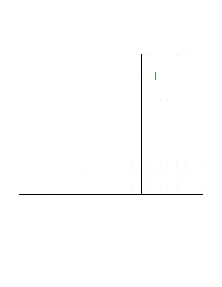
NVH Troubleshooting Chart

INFOID:0000000006225415

Use chart below to find the cause of the symptom. If necessary, repair or replace these parts.

×

: Applicable

Reference

F

AX-8

F

AX-7

NVH in

 F

AX an

d F

S

U

 s

e

c

ti

o

ns

NVH in WT section

NVH in WT section

NVH in B

R

 section

NVH in S

T

 section

Possible cause and SUSPECTED PARTS

Im

p

rop

er i

n

s

ta

lla

tio

n

lo

os

en

es

s

P

a

rt

s interference

W

he

el be

arin

g da

ma

ge

F

R

ONT

 AXLE AND FRONT S

U

SPENSION

TI

RE

ROAD W

H

EEL

BR

AK

E

S

T

EERING

Symptom

FRONT AXLE

Noise

×

×

×

×

×

×

×

×

Shake

×

×

×

×

×

×

×

×

Vibration

×

×

×

×

×

×

Shimmy

×

×

×

×

×

×

×

Judder

×

×

×

×

×

×

Poor quality ride or handling

×

×

×

×

×

FRONT WHEEL HUB AND KNUCKLE

FAX-7

< PERIODIC MAINTENANCE >

[2WD]

C

E

F

G

H

I

J

K

L

M

A

B

FAX

N

O

P

PERIODIC MAINTENANCE

FRONT WHEEL HUB AND KNUCKLE

Inspection

INFOID:0000000006225416

MOUNTING INSPECTION

Make sure that the mounting conditions (looseness, backlash) of each component and component conditions
(wear, damage) are normal.

WHEEL BEARING INSPECTION

• Move wheel hub and bearing assembly in the axial direction by hand. Make sure there is no looseness of

wheel hub and bearing assembly.

• Rotate wheel hub and bearing assembly and make sure that is no unusual noise or other irregular condi-

tions. If there is any of irregular conditions, replace wheel hub and bearing assembly.

Axial end play

: Refer to 

FAX-10, "Wheel Hub and Bearing Assembly"

.

FAX-8

< REMOVAL AND INSTALLATION >

[2WD]

FRONT WHEEL HUB AND KNUCKLE

REMOVAL AND INSTALLATION

FRONT WHEEL HUB AND KNUCKLE

Exploded View

INFOID:0000000006225418

Removal and Installation

INFOID:0000000006225419

REMOVAL

1.

Remove tires with power tool. Refer to 

WT-64, "Removal and Installation"

.

2.

Remove brake hose bracket. Refer to 

BR-23, "FRONT : Removal and Installation"

.

3.

Remove caliper assembly mounting bolts. Hang caliper assembly in a place where it will not interfere with
work. Refer to 

BR-37, "BRAKE CALIPER ASSEMBLY : Removal and Installation"

.

CAUTION:

Never depress brake pedal while brake caliper is removed.

4.

Remove disc rotor.

CAUTION:

• Put matching marks on the wheel hub and bearing assembly and the disc rotor before removing

the disc rotor.

• Never drop disc rotor.

5.

Remove wheel sensor harness. Refer to 

BRC-134, "FRONT WHEEL SENSOR : Removal and Installa-

tion"

.

CAUTION:

Never pull on wheel sensor harness.

6.

Remove steering outer socket. Refer to 

ST-42, "Removal and Installation"

.

7.

Set suitable jack under lower link.

1.

Steering knuckle

2.

Cotter pin

3.

Splash guard

4.

Hub bolt

5.

Wheel hub and bearing assembly

6.

Disc rotor

Refer to 

GI-4, "Components"

 for symbols in the figure.

JPDIF0294GB

FRONT WHEEL HUB AND KNUCKLE

FAX-9

< REMOVAL AND INSTALLATION >

[2WD]

C

E

F

G

H

I

J

K

L

M

A

B

FAX

N

O

P

8.

Remove shock absorber mounting bolt from lower link. Refer to 

FSU-10, "Removal and Installation"

.

9.

Separate upper link from steering knuckle, using the ball joint remover (commercial service tool), and
remove upper link.

CAUTION:

• Temporarily tighten the nut to prevent damage to threads and to prevent the ball joint remover

from suddenly coming off.

• Never damage ball joint boot.

10. Remove wheel hub and bearing assembly, and then remove splash guard.

11. Remove lower link from steering knuckle.

CAUTION:

Never damage ball joint boot.

12. Remove steering knuckle.
13. Remove hub bolts (1) from wheel hub and bearing assembly,

using the ball joint remover (A) (commercial service tool). 

CAUTION:

• Remove hub bolt only when necessary.
• Never hammer the hub bolt to avoid impact to the wheel

hub and bearing assembly.

• Pull out the hub bolt in a direction perpendicular to the

wheel hub and bearing assembly.

14. Perform inspection after removal. Refer to 

FAX-9, "Inspection"

.

INSTALLATION

Note the following, and install in the reverse order of removal.
• Place a suitable washer (A) as shown in the figure to install the hub

bolts (1) by using the tightening force of the nut (B).

CAUTION:

• Check that there is no clearance between wheel hub and

bearing assembly, and hub bolt. 

• Never reuse hub bolt.

• Perform the final tightening of each of parts under unladen condi-

tions, which were removed when removing wheel hub and bearing
assembly and steering knuckle.

• Never reuse cotter pin.
• Perform inspection after installation. Refer to 

FAX-9, "Inspection"

.

Inspection

INFOID:0000000006225420

INSPECTION AFTER REMOVAL

Check components for deformation, cracks, and other damage. Replace it if necessary.

Ball Joint Inspection

Check boots of lower link and steering outer socket ball joint for breakage, axial play, and torque. Refer to

FSU-15, "Inspection"

 and 

ST-46, "Inspection"

.

INSPECTION AFTER INSTALLATION

1.

Check wheel sensor harness for proper connection. Refer to 

BRC-134, "FRONT WHEEL SENSOR :

Exploded View"

.

2.

Check the wheel alignment. Refer to 

FSU-7, "Inspection"

.

3.

Adjust neutral position of steering angle sensor. Refer to 

BRC-64, "Work Procedure"

.

JPDIF0299ZZ

JPDIF0300ZZ


Content   ..  724  725  726  727   ..