Infiniti QX56 (Z62). Manual - part 702


  Index      Infiniti     Infiniti QX56 (Z62) - service repair manual 2011 year


Search            


Content   ..  700  701  702  703   ..


Infiniti QX56 (Z62). Manual - part 702


EXL-100

< DTC/CIRCUIT DIAGNOSIS >

[XENON TYPE]

TURN SIGNAL LAMP CIRCUIT

3.

CHECK TURN SIGNAL LAMP OPEN CIRCUIT

1.

Turn ignition switch OFF.

2.

Disconnect BCM connector.

3.

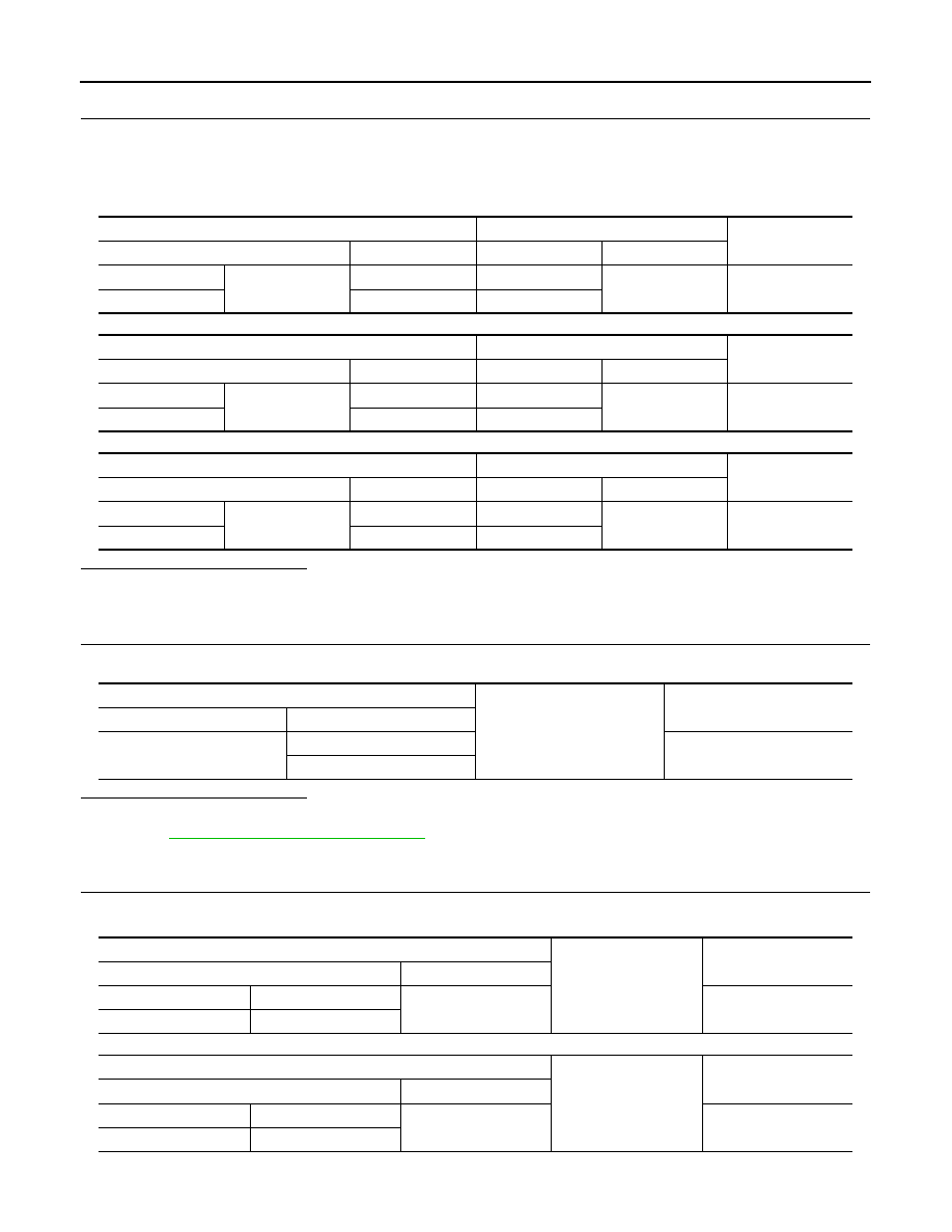
Check continuity between BCM harness connector and front combination lamp, door mirror or rear combi-
nation lamp harness connector.

Front turn signal lamp

Side turn signal lamp

Rear turn signal lamp

Is the inspection result normal?

YES

>> GO TO 5.

NO

>> Repair or replace harness.

4.

CHECK TURN SIGNAL LAMP SHORT CIRCUIT

Check continuity between BCM harness connector and ground.

Is the inspection result normal?

YES

>> Check each bulb socket for internal short circuit. Replace BCM if check result is normal. Refer to

BCS-81, "Removal and Installation"

.

NO

>> Repair or replace harness.

5.

CHECK TURN SIGNAL LAMP GROUND OPEN CIRCUIT

Check continuity between front combination lamp, door mirror or rear combination lamp and ground.

Front turn signal lamp

Side turn signal lamp

BCM

Front combination lamp 

Continuity

Connector

Terminal

Connector

Terminal

 LH

M70

60

E118

8

Existed

 RH

61

E119

BCM

Door mirror 

Continuity

Connector

Terminal

Connector

Terminal

 Driver side

M70

60

D3

20

Existed

Passenger side

61

D23

BCM

Rear combination lamp

Continuity

Connector

Terminal

Connector

Terminal

LH

M70

60

B60

3

Existed

RH

61

B232

BCM

Ground

Continuity

Connector

Terminal

M70

60

Not existed

61

Front combination lamp

Ground

Continuity

Connector

Terminal

LH

E118

3

Existed

RH

E119

Door mirror

Ground

Continuity

Connector

Terminal

Driver side

D3

19

Existed

Passenger side

D23

TURN SIGNAL LAMP CIRCUIT

EXL-101

< DTC/CIRCUIT DIAGNOSIS >

[XENON TYPE]

C

D

E

F

G

H

I

J

K

M

A

B

EXL

N

O

P

Rear turn signal lamp

Is the inspection result normal?

YES

>> Check corresponding bulb socket and harness. Repair or replace if necessary.

NO

>> Repair or replace harness.

Rear combination lamp

Ground

Continuity

Connector

Terminal

LH

B60

4

Existed

RH

B232

EXL-102

< DTC/CIRCUIT DIAGNOSIS >

[XENON TYPE]

OPTICAL SENSOR

OPTICAL SENSOR

Component Function Check

INFOID:0000000006213969

1.

CHECK OPTICAL SENSOR SIGNAL BY CONSULT-III

CONSULT-III DATA MONITOR

1.

Turn ignition switch ON.

2.

Select “OPTISEN (DTCT)” of BCM (HEADLAMP) data monitor item.

3.

Turn lighting switch AUTO.

4.

With the optical sensor illuminating, check the monitor status. 

*: Illuminates the optical sensor. The value may be less than the standard value if brightness is weak.

Is the inspection result normal?

YES

>> Optical sensor is normal.

NO

>> Refer to 

EXL-102, "Diagnosis Procedure"

.

Diagnosis Procedure

INFOID:0000000006213970

1.

CHECK OPTICAL SENSOR POWER SUPPLY INPUT

1.

Turn ignition switch ON.

2.

Turn lighting switch AUTO.

3.

Check voltage between optical sensor harness connector and ground.

Is the inspection result normal?

YES

>> GO TO 2.

NO

>> GO TO 4.

2.

CHECK OPTICAL SENSOR GROUND INPUT

Check voltage between optical sensor harness connector and ground.

Is the inspection result normal?

YES

>> GO TO 3.

NO

>> GO TO 6.

3.

CHECK OPTICAL SENSOR SIGNAL OUTPUT

 With illuminating the optical sensor, check voltage between optical sensor harness connector and ground.

Monitor item

Condition

Voltage (Approx.)

OPTISEN (DTCT)

Optical sensor

When illuminating

3.1 V or more *

When shutting off light

0.6 V or less

(+)

(

)

Voltage

(Approx.)

Optical sensor

Connector

Terminal

M17

1

Ground

5 V

(+)

(

)

Voltage

(Approx.)

Optical sensor

Connector

Terminal

M17

3

Ground

0 V

OPTICAL SENSOR

EXL-103

< DTC/CIRCUIT DIAGNOSIS >

[XENON TYPE]

C

D

E

F

G

H

I

J

K

M

A

B

EXL

N

O

P

*: Illuminate the optical sensor. The value may be less than the standard if brightness is weak.

Is the inspection result normal?

YES

>> GO TO 7.

NO

>> Replace the optical sensor.

4.

CHECK OPTICAL SENSOR OPEN CIRCUIT

1.

Turn ignition switch OFF.

2.

Disconnect optical sensor connector and BCM connector.

3.

Check continuity between optical sensor harness connector and BCM harness connector.

Is the inspection result normal?

YES

>> GO TO 5.

NO

>> Repair or replace harness.

5.

CHECK OPTICAL SENSOR SHORT CIRCUIT

Check continuity between optical sensor harness connector and ground.

Is the inspection result normal?

YES

>> Replace BCM. Refer to 

BCS-81, "Removal and Installation"

.

NO

>> Repair or replace harness.

6.

CHECK OPTICAL SENSOR GROUND OPEN CIRCUIT

1.

Turn ignition switch OFF.

2.

Disconnect optical sensor connector and BCM connector.

3.

Check continuity between optical sensor harness connector and BCM harness connector.

Is the inspection result normal?

YES

>> Replace BCM. Refer to 

BCS-81, "Removal and Installation"

.

NO

>> Repair or replace harness.

7.

CHECK OPTICAL SENSOR SIGNAL OPEN CIRCUIT 

1.

Turn ignition switch OFF.

2.

Disconnect optical sensor connector and BCM connector.

3.

Check continuity between optical sensor harness connector and BCM harness connector.

(+)

(

)

Condition

Voltage

(Approx.)

Optical sensor

Connector

Terminal

M17

2

Ground

Optical sensor

When illuminating

3.1 V or more *

When shutting off light

0.6 V or less

Optical sensor

BCM

Continuity

Connector

Terminal

Connector

Terminal

M17

1

M68

17

Existed

Optical sensor

Ground

Continuity

Connector

Terminal

M17

1

Not existed

Optical sensor

BCM

Continuity

Connector

Terminal

Connector

Terminal

M17

3

M68

18

Existed


Content   ..  700  701  702  703   ..