Infiniti QX56 (Z62). Manual - part 666


  Index      Infiniti     Infiniti QX56 (Z62) - service repair manual 2011 year


Search            


Content   ..  664  665  666  667   ..


Infiniti QX56 (Z62). Manual - part 666


EM-104

< UNIT DISASSEMBLY AND ASSEMBLY >

ENGINE STAND SETTING

7.

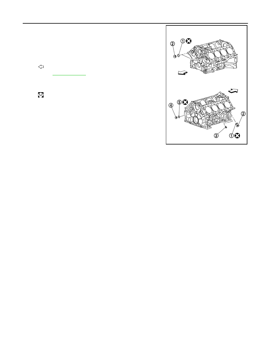
Drain engine coolant by removing water drain plug (3) from both
sides of the cylinder block as shown in the figure.

1

:  Washer

2

: Plug (engine coolant)

4

: Plug (engine oil)

5

:  Washer

: Engine front

Refer to 

GI-4, "Components"

 for symbol marks in the figure.

Water drain plug torque

: 19.6 N·m (2.0 kg/m, 14 ft-lb)

JPBIA3501ZZ

ENGINE UNIT

EM-105

< UNIT DISASSEMBLY AND ASSEMBLY >

C

D

E

F

G

H

I

J

K

L

M

A

EM

N

P

O

ENGINE UNIT

Disassembly

INFOID:0000000006289580

1.

Remove intake manifold. Refer to 

EM-30, "Exploded View"

.

2.

Remove exhaust manifold. Refer to 

EM-40, "Exploded View"

.

3.

Remove oil pan (lower). Refer to 

EM-54, "Exploded View"

.

4.

Remove ignition coil and spark plug. Refer to 

EM-23, "Exploded View"

.

5.

Remove rocker cover. Refer to 

EM-33, "Exploded View"

.

6.

Remove timing chain. Refer to 

EM-61, "Exploded View"

.

7.

Remove exhaust camshaft and VVEL ladder assembly. Refer to 

EM-74, "Exploded View"

.

8.

Remove cylinder head. Refer to 

EM-86, "Exploded View"

.

Assembly

INFOID:0000000006289581

Assemble in the reverse order of disassembly.

EM-106

< UNIT DISASSEMBLY AND ASSEMBLY >

CYLINDER BLOCK

CYLINDER BLOCK

Exploded View

INFOID:0000000006289582

1.

Knock sensor

2.

Cylinder block

3.

Side bolt

4.

Thrust bearing

5.

Main bearing (upper)

6.

Crankshaft key

7.

Crankshaft

8.

Main bearing (lower)

9.

Main bearing cap

JPBIA4511GB

CYLINDER BLOCK

EM-107

< UNIT DISASSEMBLY AND ASSEMBLY >

C

D

E

F

G

H

I

J

K

L

M

A

EM

N

P

O

Disassembly and Assembly

INFOID:0000000006289583

DISASSEMBLY

1.

Remove the following parts:
• Oil pans (lower and upper): Refer to 

EM-54, "Exploded View"

 and 

EM-57, "Exploded View"

.

• Front cover and timing chain: Refer to 

EM-61, "Exploded View"

.

• Cylinder head: Refer to 

EM-86, "Exploded View"

.

2.

Remove knock sensor.

CAUTION:

Carefully handle knock sensor avoiding shocks.

3.

Remove oil filter (for VVEL ladder assembly) from cylinder block, if necessary. Refer to 

EM-86, "Exploded

View"

.

4.

Remove piston and connecting rod assembly as per the following:
• Before removing piston and connecting rod assembly, check the connecting rod side clearance. Refer to

EM-115, "Inspection"

.

CAUTION:

Be careful not to drop connecting rod bearing, and to scratch the surface.

a.

Position crankshaft pin corresponding to connecting rod to be removed onto the bottom dead center.

b.

Loosen mounting bolts, and remove connecting rod bearing cap.

c.

Using a hammer handle (A) or similar tool, push piston and con-
necting rod assembly out to the cylinder head side.

CAUTION:

Be careful not to damage the cylinder wall and crankshaft
pin, resulting from an interference of the connecting rod big
end.

5.

Remove connecting rod bearings from connecting rod and connecting rod bearing cap.

CAUTION:

• Be careful not to drop connecting rod bearing, and to scratch the surface.
• Identify installation positions, and store them without mixing them up.

6.

Remove piston rings from piston.
• Before removing piston rings, check the piston ring side clearance. Refer to 

EM-115, "Inspection"

.

10. Main bearing cap sub bolt

11. Main bearing cap bolt

12. Connecting rod cap bolt

13. Connecting rod cap

14. Connecting rod bearing

15. Connecting rod

16. Snap ring

17. Piston pin

18. Piston

19. Oil ring

20. Second ring

21. Top ring

22. Pilot converter

23. Drive plate

24. Reinforcement plate

25. Rear oil seal

26. Rear oil seal retainer

27. O-ring

28. Crankshaft position sensor (POS)

29. Cylinder block heater (for Canada)

A.

Comply with the assembly procedure 
when tightening. Refer to 

EM-107

.

B.

Chamfered

C.

Installed on transmission

: Crankshaft side

Refer to 

GI-4, "Components"

 for symbol marks in the figure.

JPBIA2475ZZ


Content   ..  664  665  666  667   ..