Infiniti QX56 (Z62). Manual - part 652
EM-48
< REMOVAL AND INSTALLATION >
FUEL INJECTOR AND FUEL TUBE
FUEL INJECTOR AND FUEL TUBE
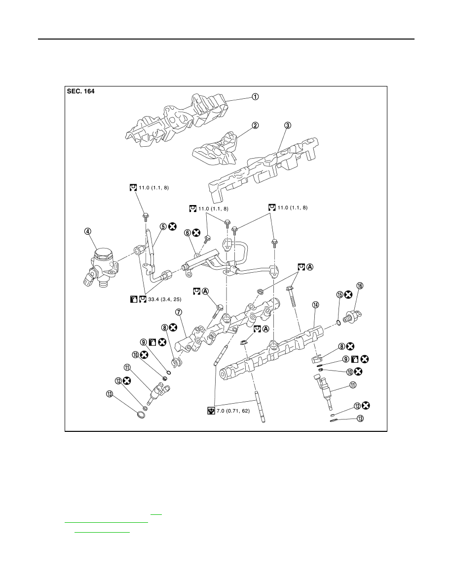
Exploded View
INFOID:0000000006289556
CAUTION:
• Never remove or disassemble parts unless instructed as shown in the figure.
• Be sure to follow the tightening instruction to avoid fuel leakage.
1.
Fuel tube insulator (bank 2)
2.
Fuel tube insulator (center)
3.
Fuel tube insulator (bank 1)
4.
High pressure fuel pump
5.
Fuel feed tube (pump side)
6.
Fuel feed tube (bank side)
7.
Fuel rail (bank 2)
8.
Injector holder
9.
O-ring (blue)
10. Backup ring
11. Fuel injector
12. Seal ring
13. Insulator
14. Fuel rail (bank 1)
15. Gasket
16. Fuel rail pressure sensor
A.
Comply with the installation proce-
dure when tightening. Refer to
49, "Removal and Installation"
.
Refer to
for symbols in the figure.
JPBIA3506GB