Infiniti QX56 (Z62). Manual - part 588


  Index      Infiniti     Infiniti QX56 (Z62) - service repair manual 2011 year


Search            


Content   ..  586  587  588  589   ..


Infiniti QX56 (Z62). Manual - part 588


EC-330

< DTC/CIRCUIT DIAGNOSIS >

[VK56VD]

P0448 EVAP CANISTER VENT CONTROL VALVE

Is the inspection result normal?

YES

>> GO TO 2.

NO

>> Clean rubber tube using an air blower.

2.

CHECK EVAP CANISTER VENT CONTROL VALVE

Refer to 

EC-327, "Component Inspection (EVAP Canister Vent Control Valve)"

.

Is the inspection result normal?

YES

>> GO TO 3.

NO

>> Replace EVAP canister vent control valve. Refer to 

FL-10, "Exploded View"

.

3.

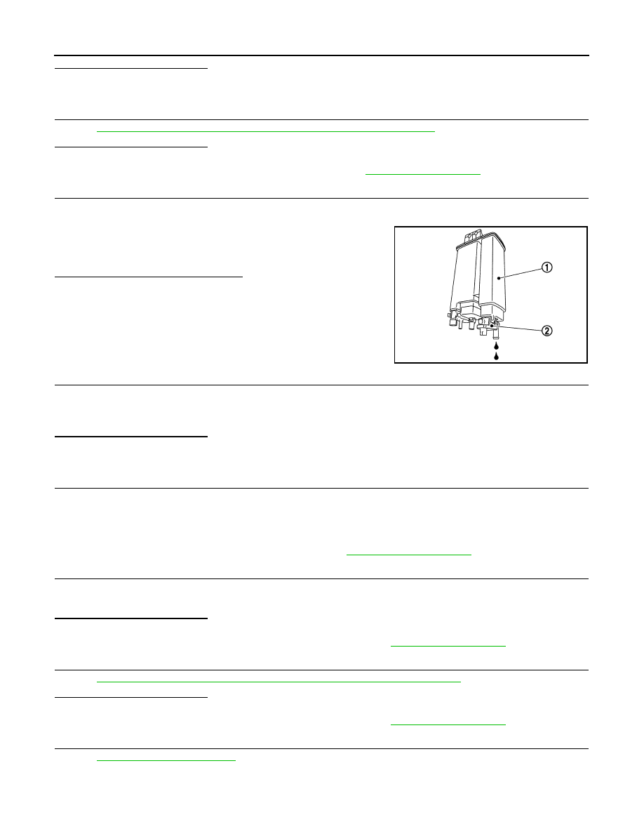
CHECK IF EVAP CANISTER IS SATURATED WITH WATER

1.

Remove EVAP canister with EVAP canister vent control valve and EVAP control system pressure sensor
attached. 

2.

Check if water will drain from the EVAP canister (1).

Does water drain from EVAP canister?

YES

>> GO TO 4.

NO

>> GO TO 6.

4.

CHECK EVAP CANISTER

Weigh the EVAP canister with the EVAP canister vent control valve and EVAP control system pressure sensor
attached.
The weight should be less than 2.5 kg (5.5 lb).
Is the inspection result normal?

YES

>> GO TO 6.

NO

>> GO TO 5.

5.

DETECT MALFUNCTIONING PART

Check the following.
• EVAP canister for damage
• EVAP hose between EVAP canister and vehicle frame for clogging or poor connection

>> Repair hose or replace EVAP canister. Refer to 

FL-10, "Hydraulic Layout"

.

6.

CHECK EVAP CONTROL SYSTEM PRESSURE SENSOR CONNECTOR

1.

Disconnect EVAP control system pressure sensor harness connector.

2.

Check that water is not inside connectors.

Is the inspection result normal?

YES

>> GO TO 7.

NO

>> Replace EVAP control system pressure sensor. Refer to 

FL-10, "Exploded View"

.

7.

CHECK EVAP CONTROL SYSTEM PRESSURE SENSOR

Refer to 

EC-335, "Component Inspection (EVAP Control System Pressure Sensor)"

.

Is the inspection result normal?

YES

>> GO TO 8.

NO

>> Replace EVAP control system pressure sensor. Refer to 

FL-10, "Exploded View"

.

8.

CHECK INTERMITTENT INCIDENT

Refer to 

GI-40, "Intermittent Incident"

.

>> INSPECTION END

2

: EVAP canister vent control valve

JSBIA0692ZZ

P0448 EVAP CANISTER VENT CONTROL VALVE

EC-331

< DTC/CIRCUIT DIAGNOSIS >

[VK56VD]

C

D

E

F

G

H

I

J

K

L

M

A

EC

N

P

O

Component Inspection (EVAP Canister Vent Control Valve)

INFOID:0000000006288362

1.

CHECK EVAP CANISTER VENT CONTROL VALVE-I

1.

Turn ignition switch OFF.

2.

Remove EVAP canister vent control valve from EVAP canister.

3.

Check portion (A) of EVAP canister vent control valve for rust.

Is it rusted?

YES

>> Replace EVAP canister vent control valve. Refer to 

FL-

10, "Exploded View"

.

NO

>> GO TO 2.

2.

CHECK EVAP CANISTER VENT CONTROL VALVE-II

 WITH CONSULT-III

1.

Reconnect harness connectors disconnected.

2.

Turn ignition switch ON.

3.

Perform “VENT CONTROL/V” in “ACTIVE TEST” mode.

4.

Check air passage continuity and operation delay time.
Check that new O-ring is installed properly.

Operation takes less than 1 second.

 WITHOUT CONSULT-III

1.

Disconnect EVAP canister vent control valve harness connector.

2.

Check air passage continuity and operation delay time under the following conditions.
Check that new O-ring is installed properly.

Operation takes less than 1 second.

Is the inspection result normal?

YES

>> GO TO 3.

NO

>> Replace EVAP canister vent control valve. Refer to 

FL-10, "Exploded View"

.

3.

CHECK EVAP CANISTER VENT CONTROL VALVE-III

 WITH CONSULT-III

1.

Clean the air passage [portion (A) to (B)] of EVAP canister vent control valve using an air blower.

2.

Perform “VENT CONTROL/V” in “ACTIVE TEST” mode.

JSBIA0693ZZ

VENT CONTROL/V Condition

Air passage continuity between (A) and (B)

ON

Not existed

OFF

Existed

JSBIA0694ZZ

Condition

Air passage continuity between (A) and (B)

12 V direct current supply between
 terminals 1 and 2

Not existed

OFF

Existed

EC-332

< DTC/CIRCUIT DIAGNOSIS >

[VK56VD]

P0448 EVAP CANISTER VENT CONTROL VALVE

3.

Check air passage continuity and operation delay time.
Check that new O-ring is installed properly.

Operation takes less than 1 second.

 WITHOUT CONSULT-III

1.

Clean the air passage [portion (A) to (B)] of EVAP canister vent control valve using an air blower.

2.

Check air passage continuity and operation delay time under the following conditions.
Check that new O-ring is installed properly.

Operation takes less than 1 second.

Is the inspection result normal?

YES

>> INSPECTION END

NO

>> Replace EVAP canister vent control valve. Refer to 

FL-10, "Exploded View"

.

VENT CONTROL/V Condition

Air passage continuity between (A) and (B)

ON

Not existed

OFF

Existed

JSBIA0694ZZ

Condition

Air passage continuity between (A) and (B)

12 V direct current supply between
 terminals 1 and 2

Not existed

OFF

Existed

P0451 EVAP CONTROL SYSTEM PRESSURE SENSOR

EC-333

< DTC/CIRCUIT DIAGNOSIS >

[VK56VD]

C

D

E

F

G

H

I

J

K

L

M

A

EC

N

P

O

P0451 EVAP CONTROL SYSTEM PRESSURE SENSOR

DTC Logic

INFOID:0000000006288316

DTC DETECTION LOGIC

DTC CONFIRMATION PROCEDURE

1.

PRECONDITIONING

1.

Turn ignition switch OFF and wait at least 10 seconds.

2.

Turn ignition switch ON.

3.

Turn ignition switch OFF and wait at least 10 seconds.

>> GO TO 2.

2.

PERFORM DTC CONFIRMATION PROCEDURE

1.

Start engine and wait at least 40 seconds.
NOTE:
Do not depress accelerator pedal even slightly.

2.

Check 1st trip DTC.

Is 1st trip DTC detected?

YES

>> Proceed to 

EC-333, "Diagnosis Procedure"

.

NO

>> INSPECTION END

Diagnosis Procedure

INFOID:0000000006288317

1.

CHECK EVAP CONTROL SYSTEM PRESSURE SENSOR CONNECTOR

1.

Disconnect EVAP control system pressure sensor harness connector.

2.

Check that water is not inside connectors.

Is the inspection result normal?

YES

>> GO TO 2.

NO

>> Repair or replace harness connector.

2.

CHECK EVAP CONTROL SYSTEM PRESSURE SENSOR POWER SUPPLY CIRCUIT

1.

Turn ignition switch ON.

2.

Check the voltage between EVAP control system pressure sensor harness connector and ground.

DTC No.

Trouble diagnosis name

(Trouble diagnosis con-

tent)

DTC detecting condition

Possible cause

P0451

EVAP SYS PRES SEN
(EVAP control system 
pressure sensor perfor-
mance)

ECM detects a sloshing signal 
from the EVAP control system 
pressure sensor

• (EVAP control system pressure sensor circuit is shorted.)

Harness or connectors
(Battery current sensor circuit is open or shorted.)
(Accelerator pedal position sensor 2 circuit is shorted.)
[Camshaft position sensor (bank 1) circuit is shorted.]
(Crankshaft position sensor circuit is shorted.)
(Refrigerant pressure sensor circuit is shorted.)

• EVAP control system pressure sensor
• Battery current sensor
• Accelerator pedal position sensor
• Camshaft position sensor (bank 1)
• Crankshaft position sensor
• Refrigerant pressure sensor

EVAP control system 

pressure sensor

Ground

Voltage (V)

Connector

Terminal

C17

3

Ground

Approx. 5 V


Content   ..  586  587  588  589   ..