Infiniti QX56 (Z62). Manual - part 582


  Index      Infiniti     Infiniti QX56 (Z62) - service repair manual 2011 year


Search            


Content   ..  580  581  582  583   ..


Infiniti QX56 (Z62). Manual - part 582


EC-306

< DTC/CIRCUIT DIAGNOSIS >

[VK56VD]

P0340, P0345 CMP SENSOR

YES

>> GO TO 11

NO

>> Replace malfunctioning camshaft position sensor. Refer to 

EM-61, "Exploded View"

.

11.

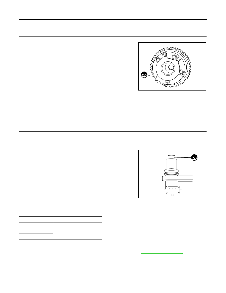
CHECK CAMSHAFT (INT)

Check the following.
• Accumulation of debris to the signal plate of camshaft front end
• Chipping signal plate of camshaft front end

Is the inspection result normal?

YES

>> GO TO 12.

NO

>> Remove debris and clean the signal plate of camshaft

front end or replace camshaft.

12.

CHECK INTERMITTENT INCIDENT

Refer to 

GI-40, "Intermittent Incident"

.

>> INSPECTION END

Component Inspection (Camshaft Position Sensor)

INFOID:0000000006217850

1.

CHECK CAMSHAFT POSITION SENSOR-I

1.

Turn ignition switch OFF.

2.

Loosen the fixing bolt of the sensor.

3.

Disconnect camshaft position sensor harness connector.

4.

Remove the sensor.

5.

Visually check the sensor for chipping.

Is the inspection result normal?

YES

>> GO TO 2.

NO

>> Replace malfunctioning camshaft position sensor.

2.

CHECK CAMSHAFT POSITION SENSOR-II

Check resistance camshaft position sensor terminals as per the following.

Is the inspection result normal?

YES

>> INSPECTION END

NO

>> Replace malfunctioning camshaft position sensor. Refer to 

EM-61, "Exploded View"

.

JMBIA0962ZZ

JMBIA0065ZZ

Terminals (Polarity)

Resistance

1 (+) - 2 (-)

Except 0 or 


 [at 25

°

C (77

°

F)]

1 (+) - 3 (-)

2 (+) - 3 (-)

P0420, P0430 THREE WAY CATALYST FUNCTION

EC-307

< DTC/CIRCUIT DIAGNOSIS >

[VK56VD]

C

D

E

F

G

H

I

J

K

L

M

A

EC

N

P

O

P0420, P0430 THREE WAY CATALYST FUNCTION

DTC Logic

INFOID:0000000006217851

DTC DETECTION LOGIC

The ECM monitors the switching frequency ratio of air fuel ratio (A/F)
sensor 1 and heated oxygen sensor 2.
A three way catalyst (manifold) with high oxygen storage capacity
will indicate a low switching frequency of heated oxygen sensor 2.
As oxygen storage capacity decreases, the heated oxygen sensor 2
switching frequency will increase.
When the frequency ratio of A/F sensor 1 and heated oxygen sensor
2 approaches a specified limit value, the three way catalyst (mani-
fold) malfunction is diagnosed.

DTC CONFIRMATION PROCEDURE

1.

INSPECTION START

1.

Turn ignition switch OFF and wait at least 10 seconds.

2.

Turn ignition switch ON.

3.

Turn ignition switch OFF and wait at least 10 seconds.

Will CONSULT-III be used?

YES

>> GO TO 2.

NO

>> GO TO 6.

2.

PERFORM DTC CONFIRMATION PROCEDURE-I

 WITH CONSULT-III

TESTING CONDITION:
Do not maintain engine speed for more than the specified minutes below.
1.

Start engine and warm it up to the normal operating temperature.

2.

Turn ignition switch OFF and wait at least 10 seconds.

3.

Turn ignition switch ON.

4.

Turn ignition switch OFF and wait at least 10 seconds.

5.

Start engine and keep the engine speed between 3,500 and 4,000 rpm for at least 1 minute under no load.

6.

Let engine idle for 1 minute.

7.

Select “DATA MONITOR” mode with CONSULT-III.

8.

Check that “COOLAN TEMP/S” indicates more than 70

°

C (158

°

F).

If not, warm up engine and go to next step when “COOLAN TEMP/S” indication reaches to 70

°

C (158

°

F).

9.

Open engine hood.

10. Select “DTC & SRT CONFIRMATION” then “SRT WORK SUPPORT” mode with CONSULT-III.
11. Rev engine between 2,000 and 3,000 rpm and hold it for 3 consecutive minutes then release the acceler-

ator pedal completely.

12. Check the indication of “CATALYST”.
Which is displayed on CONSULT-III screen?

CMPLT >> GO TO 5.
INCMP >> GO TO 3.

PBIB2055E

DTC No.

Trouble diagnosis name

(Trouble diagnosis content)

DTC detecting condition

Possible cause

P0420

TW CATALYST SYS-B1
[Catalyst system efficiency 
below threshold (bank 1)]

• Three way catalyst (manifold) does not 

operate properly.

• Three way catalyst (manifold) does not 

have enough oxygen storage capacity.

• Three way catalyst (manifold)
• Exhaust tube
• Intake air leakage
• Fuel injector
• Fuel injector leakage
• Spark plug
• Improper ignition timing

P0430

TW CATALYST SYS-B2
[Catalyst system efficiency 
below threshold (bank 2)]

EC-308

< DTC/CIRCUIT DIAGNOSIS >

[VK56VD]

P0420, P0430 THREE WAY CATALYST FUNCTION

3.

PERFORM DTC CONFIRMATION PROCEDURE-II

1.

Wait 5 seconds at idle.

2.

Rev engine between 2,000 and 3,000 rpm and maintain it until “INCMP” of “CATALYST” changes to
“CMPLT” (It will take approximately 5 minutes).

Does the indication change to “CMPLT”?

YES

>> GO TO 5.

NO

>> GO TO 4.

4.

PERFORM DTC CONFIRMATION PROCEDURE AGAIN

1.

Stop engine and cool it down to less than 70

°

C (158

°

F).

2.

Perform DTC CONFIRMATION PROCEDURE again.

>> GO TO 2.

5.

PERFORM DTC CONFIRMATION PROCEDURE-III

Check 1st trip DTC.
Is 1st trip DTC detected?

YES

>> Go to 

EC-309, "Diagnosis Procedure"

.

NO

>> INSPECTION END

6.

PERFORM COMPONENT FUNCTION CHECK

 WITH GST

Perform component function check. Refer to 

EC-308, "Component Function Check"

.

NOTE:
Use component function check to check the overall function of the three way catalyst (manifold). During this
check, a 1st trip DTC might not be confirmed.

Is the inspection result normal?

YES

>> INSPECTION END

NO

>> Go to 

EC-309, "Diagnosis Procedure"

Component Function Check

INFOID:0000000006217852

1.

PERFORM COMPONENT FUNCTION CHECK

 WITH GST

1.

Start engine and warm it up to the normal operating temperature.

2.

Turn ignition switch OFF and wait at least 10 seconds.

3.

Start engine and keep the engine speed between 3,500 and 4,000 rpm for at least 1 minute under no load.

4.

Let engine idle for 1 minute.

5.

Open engine hood.

6.

Check the voltage between ECM harness connector terminals under the following conditions.

Is the inspection result normal?

YES

>> INSPECTION END

NO

>> Go to 

EC-309, "Diagnosis Procedure"

.

DTC

ECM

Condition

Voltage

Connector

+

Terminal

Terminal

P0420

F110

96

[HO2S2 

(bank 1)]

100

Keeping engine speed at 2,500 rpm 
constant under no load

The voltage fluctuation cycle takes more 
than 5 seconds.
• 1 cycle: 0.6 - 1.0 

 0 - 0.3 

 0.6 - 1.0

P0430

87

[HO2S2 

(bank 2)]

P0420, P0430 THREE WAY CATALYST FUNCTION

EC-309

< DTC/CIRCUIT DIAGNOSIS >

[VK56VD]

C

D

E

F

G

H

I

J

K

L

M

A

EC

N

P

O

Diagnosis Procedure

INFOID:0000000006217853

1.

CHECK EXHAUST SYSTEM

Visually check exhaust tubes and muffler for dents.

Is the inspection result normal?

YES

>> GO TO 2.

NO

>> Repair or replace malfunctioning part.

2.

CHECK EXHAUST GAS LEAKAGE

1.

Start engine and run it at idle.

2.

Listen for an exhaust gas leakage before the three way catalyst (manifold).

Is exhaust gas leakage detected?

YES

>> Repair or replace malfunctioning part.

NO

>> GO TO 3.

3.

CHECK INTAKE AIR LEAKAGE

Listen for an intake air leakage after the mass air flow sensor.
Is intake air leakage detected?

YES

>> Repair or replace malfunctioning part.

NO

>> GO TO 4.

4.

CHECK IDLE SPEED AND IGNITION TIMING

Check idle speed and ignition timing.
For procedure, refer to 

EC-530, "Inspection"

 and 

EC-531, "Inspection"

.

For specification, refer to 

EC-538, "Idle Speed"

 and 

EC-538, "Ignition Timing"

.

Is the inspection result normal?

YES

>> GO TO 5.

NO

>> Follow the 

EC-139, "Work Procedure"

.

5.

CHECK FUEL INJECTORS

Refer to 

EC-498, "Component Function Check"

.

Is the inspection result normal?

YES

>> GO TO 6.

NO

>> Perform 

EC-498, "Diagnosis Procedure"

.

6.

CHECK FUNCTION OF IGNITION COIL-I

CAUTION:

Perform the following procedure in a place with no combustible objects and good ventilation.
1.

Turn ignition switch OFF.

2.

Remove fuel pump fuse in IPDM E/R to release fuel pressure.
NOTE:
• For the fuse number, refer to 

EC-114, "Wiring Diagram"

.

• For the fuse arrangement, refer to 

PG-140, "Fuse, Connector and Terminal Arrangement"

.

• Do not use CONSULT-III to release fuel pressure, or fuel pressure applies again during the following

procedure.

3.

Start engine.

4.

After engine stalls, crank it 2 or 3 times to release all fuel pressure.

5.

Turn ignition switch OFF.

PBIB1216E


Content   ..  580  581  582  583   ..