Infiniti QX56 (Z62). Manual - part 577


  Index      Infiniti     Infiniti QX56 (Z62) - service repair manual 2011 year


Search            


Content   ..  575  576  577  578   ..


Infiniti QX56 (Z62). Manual - part 577


EC-286

< DTC/CIRCUIT DIAGNOSIS >

[VK56VD]

P0197, P0198 EOT SENSOR

YES

>> GO TO 3.

NO

>> Repair open circuit, short to ground or short to power in harness or connectors.

3.

CHECK ENGINE OIL TEMPERATURE SENSOR

Refer to 

EC-286, "Component Inspection (Engine Oil Temperature Sensor)"

.

Is the inspection result normal?

YES

>> GO TO 4.

NO

>> Replace engine oil temperature sensor. Refer to 

EM-54, "Exploded View"

.

4.

CHECK INTERMITTENT INCIDENT

Refer to 

GI-40, "Intermittent Incident"

.

>> INSPECTION END

Component Inspection (Engine Oil Temperature Sensor)

INFOID:0000000006217834

1.

CHECK ENGINE OIL TEMPERATURE SENSOR

1.

Turn ignition switch OFF.

2.

Disconnect engine oil temperature sensor harness connector.

3.

Remove engine oil temperature sensor.
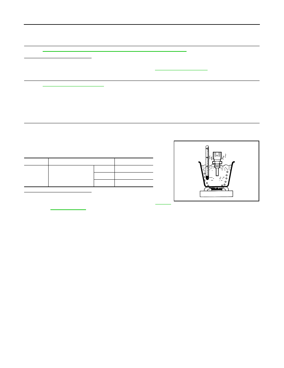
4.

Check resistance between engine oil temperature sensor termi-
nals by heating with hot water as shown in the figure.

Is the inspection result normal?

YES

>> INSPECTION END

NO

>> Replace engine oil temperature sensor. Refer to 

EM-54,

"Exploded View"

.

Terminals

Condition

Resistance (k

)

1 and 2

Temperature [

°

C (

°

F)]

20 (68)

2.35 - 2.73

50 (122)

0.68 - 1.00

90 (194)

0.236 - 0.260

JMBIA0080ZZ

P0201, P0202, P0203, P0204, P0205, P0206, P0207, P0208 INJECTOR

EC-287

< DTC/CIRCUIT DIAGNOSIS >

[VK56VD]

C

D

E

F

G

H

I

J

K

L

M

A

EC

N

P

O

P0201, P0202, P0203, P0204, P0205, P0206, P0207, P0208 INJECTOR

DTC Logic

INFOID:0000000006217835

DTC DETECTION LOGIC

DTC CONFIRMATION PROCEDURE

1.

PRECONDITIONING

1.

Turn ignition switch OFF and wait at least 10 seconds.

2.

Turn ignition switch ON.

3.

Turn ignition switch OFF and wait at least 10 seconds.

TESTING CONDITION:
Before performing the following procedure, comfirm that battery voltage is 11 V or more at idle.

>> GO TO 2.

2.

PERFORM DTC CONFIRMATION PROCEDURE

1.

Turn ignition switch OFF and wait at least 10 seconds.

2.

Start the engine and let it idle at least 30 seconds.

3.

Check 1st trip DTC.

Is 1st trip DTC detected?

YES

>> Proceed to 

EC-287, "Diagnosis Procedure"

.

NO

>> INSPECTION END

Diagnosis Procedure

INFOID:0000000006217836

1.

PERFORM TROUBLE DIAGNOSIS FOR INJECTOR

Refer to 

EC-498, "Component Function Check"

.

Is inspection result normal?

YES

>> Check intermittent incident. Refer to 

GI-40, "Intermittent Incident"

.

NO

>> Repair or replace error-detected parts.

DTC No.

Trouble diagnosis name

DTC detecting condition

Possible cause

P0201

No.1 fuel injector circuit

ECM detects No. 1 injector circuit 
is open or shorted.

• The fuel injector circuit is open or shorted
• Fuel injector
• ECM

P0202

No. 2 fuel injector circuit

ECM detects No. 2 injector circuit 
is open or shorted.

P0203

No. 3 fuel injector circuit

ECM detects No. 3 injector circuit 
is open or shorted.

P0204

No. 4 fuel injector circuit

ECM detects No. 4 injector circuit 
is open or shorted.

P0205

No. 5 fuel injector circuit

ECM detects No. 5 injector circuit 
is open or shorted.

P0206

No. 6 fuel injector circuit

ECM detects No. 6 injector circuit 
is open or shorted.

P0207

No. 7 fuel injector circuit

ECM detects No. 7 injector circuit 
is open or shorted.

P0208

No. 8 fuel injector circuit

ECM detects No. 8 injector circuit 
is open or shorted.

EC-288

< DTC/CIRCUIT DIAGNOSIS >

[VK56VD]

P0222, P0223 TP SENSOR

P0222, P0223 TP SENSOR

DTC Logic

INFOID:0000000006217837

DTC DETECTION LOGIC

NOTE:
If DTC P0222 or P0223 is displayed with DTC P0643, perform the trouble diagnosis for DTC P0643.
Refer to 

EC-381, "DTC Logic"

.

DTC CONFIRMATION PROCEDURE

1.

PRECONDITIONING

If DTC Confirmation Procedure has been previously conducted, always turn ignition switch OFF and wait at
least 10 seconds before conducting the next test.
TESTING CONDITION:
Before performing the following procedure, confirm that battery voltage is 8 V or more at idle.

>> GO TO 2.

2.

PERFORM DTC CONFIRMATION PROCEDURE

1.

Start engine and let it idle for 1 second.

2.

Check DTC.

Is DTC detected?

YES

>> Go to 

EC-288, "Diagnosis Procedure"

.

NO

>> INSPECTION END

Diagnosis Procedure

INFOID:0000000006217838

1.

CHECK THROTTLE POSITION SENSOR 1 POWER SUPPLY CIRCUIT-I

1.

Disconnect electric throttle control actuator harness connector.

2.

Turn ignition switch ON.

3.

Check the voltage between electric throttle control actuator harness connector and ground.

Is the inspection result normal?

YES

>> GO TO 2.

NO

>> Repair open circuit, short to ground or short to power in harness or connectors.

2.

CHECK THROTTLE POSITION SENSOR 1 GROUND CIRCUIT FOR OPEN AND SHORT

1.

Turn ignition switch OFF.

2.

Disconnect ECM harness connector.

3.

Check the continuity between electric throttle control actuator and ECM harness connector.

DTC No.

Trouble diagnosis name

(Trouble diagnosis content)

DTC detecting condition

Possible cause

P0222

TP SEN 1/CIRC-B1
(Throttle position sensor 1 
circuit low input)

An excessively low voltage from the TP 
sensor 1 is sent to ECM.

• Harness or connectors

(TP sensor 1 circuit is open or shorted.)

• Electric throttle control actuator

(TP sensor 1)

P0223

TP SEN 1/CIRC-B1
(Throttle position sensor 1 
circuit high input)

An excessively high voltage from the TP 
sensor 1 is sent to ECM.

Electric throttle control actuator

Ground

Voltage (V)

Connector

Terminal

F66

2

Ground

Approx. 5

P0222, P0223 TP SENSOR

EC-289

< DTC/CIRCUIT DIAGNOSIS >

[VK56VD]

C

D

E

F

G

H

I

J

K

L

M

A

EC

N

P

O

4.

Also check harness for short to ground and short to power.

Is the inspection result normal?

YES

>> GO TO 3.

NO

>> Repair open circuit, short to ground or short to power in harness or connectors.

3.

CHECK THROTTLE POSITION SENSOR 1 INPUT SIGNAL CIRCUIT FOR OPEN AND SHORT

1.

Check the continuity between electric throttle control actuator and ECM harness connector.

2.

Also check harness for short to ground and short to power.

Is the inspection result normal?

YES

>> GO TO 4.

NO

>> Repair open circuit, short to ground or short to power in harness or connectors.

4.

CHECK THROTTLE POSITION SENSOR

Refer to 

EC-289, "Component Inspection (Throttle Position Sensor)"

.

Is the inspection result normal?

YES

>> GO TO 6.

NO

>> GO TO 5.

5.

REPLACE ELECTRIC THROTTLE CONTROL ACTUATOR

Replace electric throttle control actuator. Refer to 

EM-30, "Removal and Installation"

.

>> INSPECTION END

6.

CHECK INTERMITTENT INCIDENT

Refer to 

GI-40, "Intermittent Incident"

.

>> INSPECTION END

Component Inspection (Throttle Position Sensor)

INFOID:0000000006217839

1.

CHECK THROTTLE POSITION SENSOR

1.

Turn ignition switch OFF.

2.

Reconnect all harness connectors disconnected.

3.

Perform 

EC-147, "Work Procedure"

.

4.

Turn ignition switch ON.

5.

Set selector lever position to D.

6.

Check the voltage between ECM harness connector terminals under the following conditions.

Electric throttle control actuator

ECM

Continuity

Connector

Terminal

Connector

Terminal

F66

4

F110

97

Existed

Electric throttle control actuator

ECM

Continuity

Connector

Terminal

Connector

Terminal

F66

1

F110

91

Existed

ECM

Condition

Voltage (V)

Connector

+

Terminal

Terminal

F110

91

(TP sensor 1 signal)

97

(Sensor ground)

Accelerator pedal

Fully released

More than 0.36

Fully depressed

Less than 4.75

79

(TP sensor 2 signal)

Fully released

Less than 4.75

Fully depressed

More than 0.36


Content   ..  575  576  577  578   ..