Infiniti QX56 (Z62). Manual - part 454


  Index      Infiniti     Infiniti QX56 (Z62) - service repair manual 2011 year


Search            


Content   ..  452  453  454  455   ..


Infiniti QX56 (Z62). Manual - part 454


DLN-16

< SYSTEM DESCRIPTION >

[TRANSFER: ATX90A]

STRUCTURE AND OPERATION

1.

Transfer control unit supplies command current to transfer motor.

2.

Transfer motor operates and actuator shaft rotates clockwise.

3.

Shift fork operates according to rotation of actuator shaft. Sun gear and Hi-Lo sleeve are engaged.

4.

Ball ramp lever operates in axial direction via cam fixed on actuator shaft according to traction torque of
transfer motor, presses piston, and thrusts multiple plate clutch.

5.

Torque is transmitted to front wheels according to thrusting pressure of multiple plate clutch.
NOTE:
Torque transmitted to the front wheel is determined according to the command current.
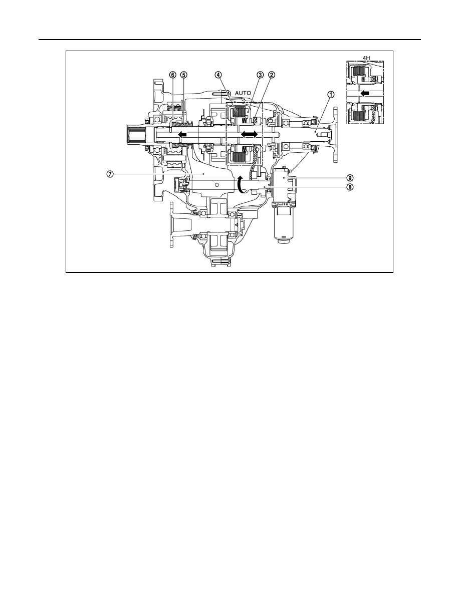
4L MODE

1.

Main shaft

2.

Ball lamp lever

3.

Piston

4.

Clutch

5.

Hi-Lo sleeve

6.

Sun gear

7.

Shift fork

8.

Actuator shaft

9.

Transfer control actuator

JPDIE0278GB

STRUCTURE AND OPERATION

DLN-17

< SYSTEM DESCRIPTION >

[TRANSFER: ATX90A]

C

E

F

G

H

I

J

K

L

M

A

B

DLN

N

O

P

1.

Transfer control unit supplies command current to transfer motor.

2.

Transfer motor operates and actuator shaft rotates counterclockwise.

3.

Shift fork operates according to rotation of actuator shaft. Planetary carrier assembly and Hi-Lo sleeve are
engaged.

1.

Main shaft

2.

Sprocket

3.

Lock sleeve

4.

Hi-Lo sleeve

5.

Sun gear

6.

Planetary carrier assembly

7.

Internal gear

8.

Shift fork

9.

Actuator shaft

10. Transfer control actuator

JPDIE0279ZZ

DLN-18

< SYSTEM DESCRIPTION >

[TRANSFER: ATX90A]

SYSTEM

SYSTEM

4WD SYSTEM

4WD SYSTEM : System Description

INFOID:0000000006222224

• In AUTO mode, distribution of traction force is controlled from 2WD status (0:100) to 4WD status (50:50)

according to signal from each sensor and switch.

• In accordance with fail-safe function, when system is malfunctioning, 4WD warning lamp on combination

meter turns ON and 4WD control stops. For fail-safe function, refer to 

DLN-20, "4WD SYSTEM : Fail-Safe"

.

• When a high load status continues for transfer assembly (transfer control actuator or transfer fluid), 4WD

control temporarily becomes 4H or 2WD status, according to protection function.
NOTE:
4WD system is not malfunctioning.

SYSTEM DIAGRAM

INPUT/OUTPUT SIGNAL

It transmits/receives each signal from the following transfer control unit via CAN communication line.

JPDIE0272GB

Component parts

Control signal

ABS actuator and electric unit (control unit)

Transmits the following signals via CAN communication line to transfer control unit.
• Vehicle speed signal (ABS)
• Stop lamp switch signal (brake signal)
• ABS operation signal
• VDC operation signal
• TCS operation signal

ECM

Transmits the following signals via CAN communication line to transfer control unit.
• Accelerator pedal position signal
• Engine speed signal
• Engine torque signal

SYSTEM

DLN-19

< SYSTEM DESCRIPTION >

[TRANSFER: ATX90A]

C

E

F

G

H

I

J

K

L

M

A

B

DLN

N

O

P

4WD SHIFT SWITCH AND 4WD SHIFT INDICATOR LAMP

*1: Blinking 2 times/1 second
*2: “4HI” and “4LO” blink alternately.

CONDITION FOR TURN ON THE WARNING LAMP

TCM

Transmits the following signals via CAN communication line to transfer control unit.
• Shift position signal
• Gear position signal
• Output shaft revolution signal

Steering angle sensor

Transmits the following signals via CAN communication line to transfer control unit.
• Steering angle sensor signal

Combination meter 

Receives the following signals via CAN communication line from transfer control unit.
• 4WD warning lamp signal
• ATP warning lamp signal
• 4WD mode indicator signal

Component parts

Control signal

4WD shift switch

4WD shift indicator lamp (in Information display)

4WD shift procedure

AUTO

1.

Start the engine.

2.

Turn the 4WD shift switch.

NOTE:
Mode can be switched between AU-
TO

4H while driving straight.

4H

↓↑

4WD status: 4H

4L

(Blinking)

*1*2

1.

Start the engine.

2.

Never drive the vehicle.

3.

Shift A/T shift selector to N position.

4.

Press and rotate 4WD shift switch 
while depressing brake pedal.

CAUTION:

4WD mode does not switch when 4WD 
shift switch is operated while the vehi-
cle is running or A/T shift selector is 
shifted to any position other than neu-
tral.

4L

JPDIE0230ZZ

JPDIE0234ZZ

JPDIE0231ZZ

JPDIE0235ZZ

JPDIE0231ZZ

JPDIE0233ZZ

JPDIE0236ZZ

JPDIE0233ZZ

JPDIE0237ZZ


Content   ..  452  453  454  455   ..