Infiniti QX56 (Z62). Manual - part 418


  Index      Infiniti     Infiniti QX56 (Z62) - service repair manual 2011 year


Search            


Content   ..  416  417  418  419   ..


Infiniti QX56 (Z62). Manual - part 418


DLK-138

< DTC/CIRCUIT DIAGNOSIS >

DOOR REQUEST SWITCH

3.

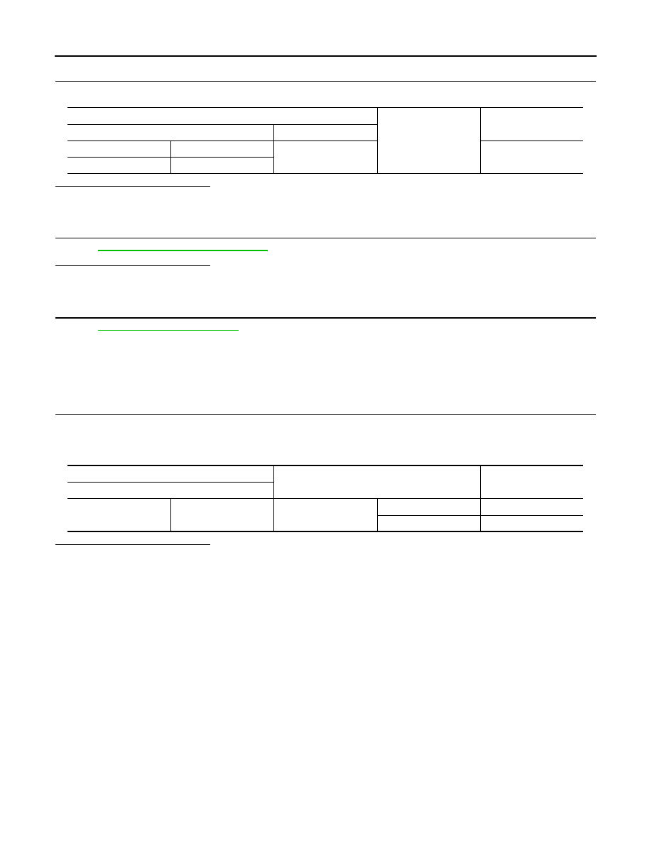
CHECK DOOR REQUEST SWITCH GROUND CIRCUIT

Check continuity between malfunctioning front door request switch harness connector and ground.

Is the inspection result normal?

YES

>> GO TO 4.

NO

>> Repair or replace harness.

4.

CHECK DOOR REQUEST SWITCH

Refer to 

DLK-138, "Component Inspection"

.

Is the inspection result normal?

YES

>> GO TO 5.

NO

>> Replace malfunctioning front door request switch.

5.

CHECK INTERMITTENT INCIDENT

Refer to 

GI-40, "Intermittent Incident"

.

>> INSPECTION END 

Component Inspection

INFOID:0000000006225951

1.

CHECK DOOR REQUEST SWITCH

1.

Turn ignition switch OFF.

2.

Disconnect malfunctioning front door request switch connector.

3.

Check continuity between malfunctioning front door request switch terminals.

Is the inspection result normal?

YES

>> INSPECTION END

NO

>> Replace malfunctioning front door request switch.

Front door request switch

Ground

Continuity 

Connector

Terminal

Driver side

D11

2

Existed

Passenger side

D31

Front door request switch

Condition

Continuity

Terminal

1

2

Door request switch

Pressed

Existed

Released

Not existed

BACK DOOR REQUEST SWITCH

DLK-139

< DTC/CIRCUIT DIAGNOSIS >

C

D

E

F

G

H

I

J

L

M

A

B

DLK

N

O

P

BACK DOOR REQUEST SWITCH

Component Function Check

INFOID:0000000006225952

1.

CHECK FUNCTION

1.

Select “INTELLIGENT KEY” of “BCM” using CONSULT-III.

2.

Select “REQ SW-BD/TR” in “DATA MONITOR” mode.

3.

Check that the function operates normally according to the following conditions.

Is the inspection result normal?

YES

>> Back door request switch is OK.

NO

>> Refer to 

DLK-139, "Diagnosis Procedure"

.

Diagnosis Procedure

INFOID:0000000006225953

1.

CHECK BACK DOOR REQUEST SWITCH INPUT SIGNAL

1.

Turn ignition switch OFF.

2.

Disconnect back door opener switch assembly connector.

3.

Check voltage between back door opener switch assembly harness connector and ground.

Is the inspection result normal?

YES

>> GO TO 3.

NO

>> GO TO 2.

2.

CHECK BACK DOOR REQUEST SWITCH CIRCUIT

1.

Disconnect BCM connector.

2.

Check continuity between BCM harness connector and back door opener switch assembly harness con-
nector.

3.

Check continuity between BCM harness connector and ground.

Is the inspection result normal?

YES

>> Replace BCM. Refer to 

BCS-81, "Removal and Installation"

.

NO

>> Repair or replace harness.

3.

CHECK BACK DOOR REQUEST SWITCH GROUND CIRCUIT

Check continuity between back door opener switch assembly harness connector and ground.

Monitor item

Condition

Status

REQ SW-BD/TR

Back door request switch

Pressed

On

Released

Off

(+)

(–)

Voltage

(Approx.)

Back door opener switch assembly

Connector

Terminal 

D154

4

Ground

12 V

BCM

Back door opener switch assembly

Continuity 

Connector

Terminal

Connector

Terminal

M69

51

D154

4

Existed

BCM

Ground

Continuity 

Connector

Terminal

M69

51

Not existed

DLK-140

< DTC/CIRCUIT DIAGNOSIS >

BACK DOOR REQUEST SWITCH

Is the inspection result normal?

YES

>> GO TO 4.

NO

>> Repair or replace harness.

4.

CHECK BACK DOOR REQUEST SWITCH

Refer to 

DLK-140, "Component Inspection"

.

Is the inspection result normal?

YES

>> GO TO 5.

NO

>> Replace back door opener switch assembly.

5.

CHECK INTERMITTENT INCIDENT

Refer to 

GI-40, "Intermittent Incident"

.

>> INSPECTION END

Component Inspection

INFOID:0000000006225954

1.

CHECK BACK DOOR REQUEST SWITCH

1.

Turn ignition switch OFF.

2.

Disconnect back door opener switch assembly connector.

3.

Check continuity between back door opener switch assembly terminals.

Is the inspection result normal?

YES

>> INSPECTION END

NO

>> Replace back door opener switch assembly.

Back door opener switch assembly

Ground

Continuity 

Connector

Terminal

D154

3

Existed

 Back door opener switch assembly

Condition

Continuity 

Terminal

3

4

Back door request switch

Pressed

Existed

Released

Not existed

BACK DOOR OPENER SWITCH

DLK-141

< DTC/CIRCUIT DIAGNOSIS >

C

D

E

F

G

H

I

J

L

M

A

B

DLK

N

O

P

BACK DOOR OPENER SWITCH

Component Function Check

INFOID:0000000006225955

1.

CHECK FUNCTION

1.

Select “TRUNK” of “BCM” using CONSULT-III.

2.

Select “TR/BD OPEN SW” in “DATA MONITOR” mode.

3.

Check that the function operates normally according to the following conditions.

Is the inspection result normal?

YES

>> Back door opener switch is OK.

NO

>> Refer to 

DLK-141, "Diagnosis Procedure"

.

Diagnosis Procedure

INFOID:0000000006225956

1.

CHECK BACK DOOR OPEN INPUT SIGNAL

1.

Turn ignition switch OFF.

2.

Disconnect back door opener switch assembly connector.

3.

Check signal between back door opener switch assembly harness connector and ground.

Is the inspection result normal?

YES

>> GO TO 3.

NO

>> GO TO 2.

2.

CHECK BACK DOOR OPENER SWITCH CIRCUIT

1.

Disconnect BCM connector.

2.

Check continuity between BCM harness connector and back door opener switch assembly harness con-
nector.

3.

Check continuity between BCM harness connector and ground.

Is the inspection result normal?

YES

>> Replace BCM. Refer to 

BCS-81, "Removal and Installation"

.

NO

>> Repair or replace harness.

Monitor item

Condition

Status

TR/BD OPEN SW

Back door opener switch

Pressed

ON

Released

OFF

(+)

(–)

Signal

(Reference value)

Back door opener switch assembly

Connector

Terminal 

D154

1

Ground

JPMIA0012GB

BCM

Back door opener switch assembly

Continuity 

Connector

Terminal

Connector

Terminal

M68

30

D154

1

Existed

BCM

Ground

Continuity 

Connector

Terminal

M68

30

Not existed


Content   ..  416  417  418  419   ..