Infiniti QX56 (Z62). Manual - part 412
DLK-114
< DTC/CIRCUIT DIAGNOSIS >
B2628 OUTSIDE ANTENNA
B2628 OUTSIDE ANTENNA
DTC Logic
INFOID:0000000006225918
DTC DETECTION LOGIC
DTC CONFIRMATION PROCEDURE
1.
PERFORM DTC CONFIRMATION PROCEDURE
1.
Turn ignition switch ON.
2.
Check “Self Diagnostic Result” mode of “BCM” using CONSULT-III.
Is DTC detected?
YES
>> Refer to
DLK-108, "Diagnosis Procedure"
.
NO
>> Outside key antenna (back door) is OK.
Diagnosis Procedure
INFOID:0000000006225919
1.
CHECK OUTSIDE KEY ANTENNA INPUT SIGNAL 1
1.
Turn ignition switch OFF.
2.
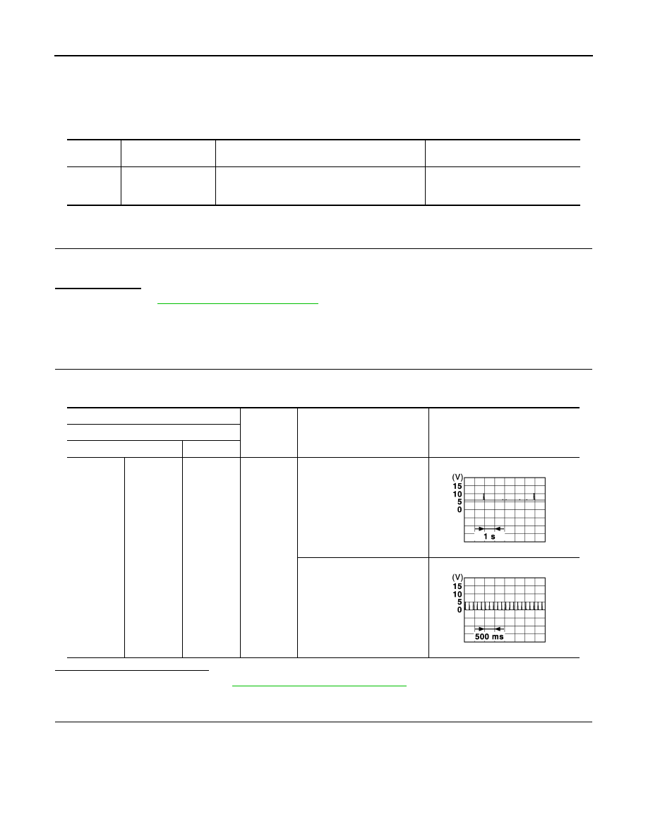
Check signal between BCM harness connector and ground using oscilloscope.
Is the inspection result normal?
YES
>> Replace BCM. Refer to
BCS-81, "Removal and Installation"
NO
>> GO TO 2.
2.
CHECK OUTSIDE KEY ANTENNA CIRCUIT
1.
Disconnect BCM connector and outside key antenna (back door) connector.
2.
Check continuity between BCM harness connector and outside key antenna (back door) harness connec-
tor.
DTC
CONSULT-III display
description
DTC detecting condition
Possible cause
B2628
OUTSIDE ANTENNA
An excessive high or low voltage from outside key
antenna (back door) is sent to BCM
• Outside key antenna (back door)
• Between BCM – Outside key an-
tenna (back door)
(+)
(–)
Condition
Signal
(Reference value)
BCM
Connector
Terminal
Back door
M71
82, 83
Ground
When Intelligent Key is in the
antenna detection area
When Intelligent Key is not in
the antenna detection area
JMKIA3839GB
JMKIA3838GB