Infiniti QX56 (Z62). Manual - part 374
DEF-6
< SYSTEM DESCRIPTION >
SYSTEM
SYSTEM
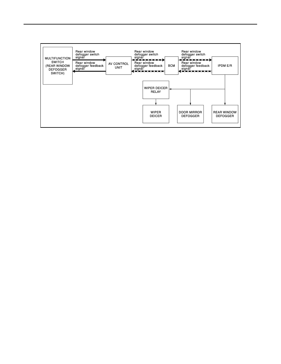
System Diagram
INFOID:0000000006299425
System Description
INFOID:0000000006299426
System Description
• Multifunction switch (rear window defogger switch) transmits rear window defogger switch signal to AV con-
trol unit via AV communication when rear window defogger switch is turned ON, while ignition switch is ON.
AV control unit transmits rear window defogger switch signal to BCM via CAN communication.
• BCM transmits rear defogger window switch signal to IPDM E/R for approximately 15 minutes via CAN com-
munication when rear window defogger switch signal is received.
• IPDM E/R turns rear window defogger relay ON when rear window defogger switch signal is received.
• Power supply is supplied to rear window defogger and door mirror defoggers when rear window defogger
relay is ON.
• Wiper deicer relay turns ON when rear window defogger relay is ON.
• Power is supply to wiper deicer when wiper deicer relay is ON.
• AV control unit transmits rear window defogger control signal to multifunction switch (rear window defogger
switch) via AV communication.
• IPDM E/R transmits rear window defogger control signal to AV control unit via CAN communication.
Timer function
• BCM turns rear window defogger relay ON for approximately 15 minutes when rear window defogger switch
is turned ON to operate rear window defogger, door mirror defoggers and wiper deicer.
• Timer is canceled when rear window defogger switch is pressed again during timer operation. BCM turns
rear window defogger relay OFF. The same operation also occurs when the ignition switch is turned OFF
during timer operation.
JMLIA0981GB